MF877-00 Page 3
Template Revision C, 30-July-2018
Copyright 2018 Hewlett Packard Enterprise Development LP
HPE instructions for this template are available at
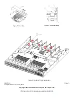
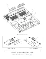
18. Unscrew the screws (qty 14) with a T-10 driver, that secure the main PCA to the base (Figure 14)
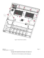
19. Remove the main PCA from the base. Remove the small heatsink by unclipping the two wire bails from the main PCA,
then twist and untwist a couple of times to remove the heatsink from the thermal interface material and unscrew the 8
screws fr the heatsink and remove the heatsink by twisting and untwisting a couple of times. (Figure 15)
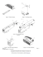
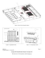
20. At the front right corner of the main PCA, remove the front plastic lightpiple (Figure 16)
21. On the empty chassis front right, remove the 2 lightpipe (Figure 17).
3.2 Optional Graphic. If the disassembly process is complex, insert a graphic illustration below to identify the items
contained in the product that require selective treatment (with descriptions and arrows identifying locations).
Figure 1: Chassis screw locations

