USB Bus Driver: 00000020
USB Bot Mass Storage Driver: 00000020
Generic USB Mass Storage Driver: 00000020
CLPrelay App: 00000100
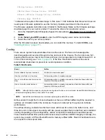
* Indicates active system firmware image. In this case =>3.02 indicates that this server does not
need system firmware updated to use the memory modules described in this document.
The firmware upgrade instructions are included in the Release Notes on the firmware package
download page for your server product. To locate the drivers for a particular server.
1.
Go to the Hewlett Packard Enterprise Support Center website:
2.
Under
Select your HPE product
, enter the HPE Integrity server name and click
Go
.
3.
Select the link for your server product.
After the firmware has been downloaded, you can install the memory. To install DIMMs, see
“Installing Memory” (page 211)
Cooling
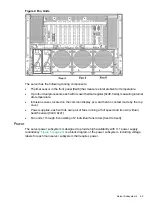
There are six system fans assemblies that cool the server. The fans are hot-swappable,
interchangeable and serviced through the top and rear of the chassis. The fan rotors are N+1,
meaning that the server has 12 fan rotors (six fans), but can operate for a limited time with 11 or
10 fan rotors running, see
. If the time threshold is reached, the server
automatically shuts down to prevent an overtemperature condition.
Table 5 Fan Events
Action
Event
All rotors to maximum speed
1
Server chassis top cover removed
All remaining rotors to maximum speed
One fan rotor fails or is too slow
All remaining rotors to maximum speed and hard shut down after two
minutes of continuous failure
Two or more fan motors fail or are too
slow
All remaining rotors to maximum speed and hard shut down after two
minutes of continuous failure
2
One or more fan units removed
1
NOTE:
Although the fans speed up to provide cooling when the top cover is removed, Hewlett Packard Enterprise
recommends replacing the top cover within 15 seconds.
2
NOTE:
Hewlett Packard Enterprise recommends replacing fans within 20 seconds.
Airflow enters through the front and exhausts out the rear. Airflow baffles might be required to
optimize air circulation within the enclosure. Fans are monitored by the system to indicate
performance.
The airflow strategy contains two thermal zones with three fan units in the bottom zone, and
three fan units in the upper zone along with two power supplies that provide their own individual
cooling. Depending on the configuration, certain component locations will need filler panels.
These installed airflow filler panels and blockers ensure airflow and EMI integrity. Internally, the
system may require a CPU airflow baffle and a memory airflow baffle. Rear I/O bulkhead covers
are required in unoccupied slots.
22
Overview

