background image

23 


When the IRF virtual device operates normally, only the MAD IP address of the master is effective 
and the BFD session is down. 


When the IRF virtual device partitions, the MAD IP addresses of the masters in different IRF virtual 
devices become effective to activate the BFD sessions to detect for multi-active IRF virtual device 

collision. 

2.


Network requirements 

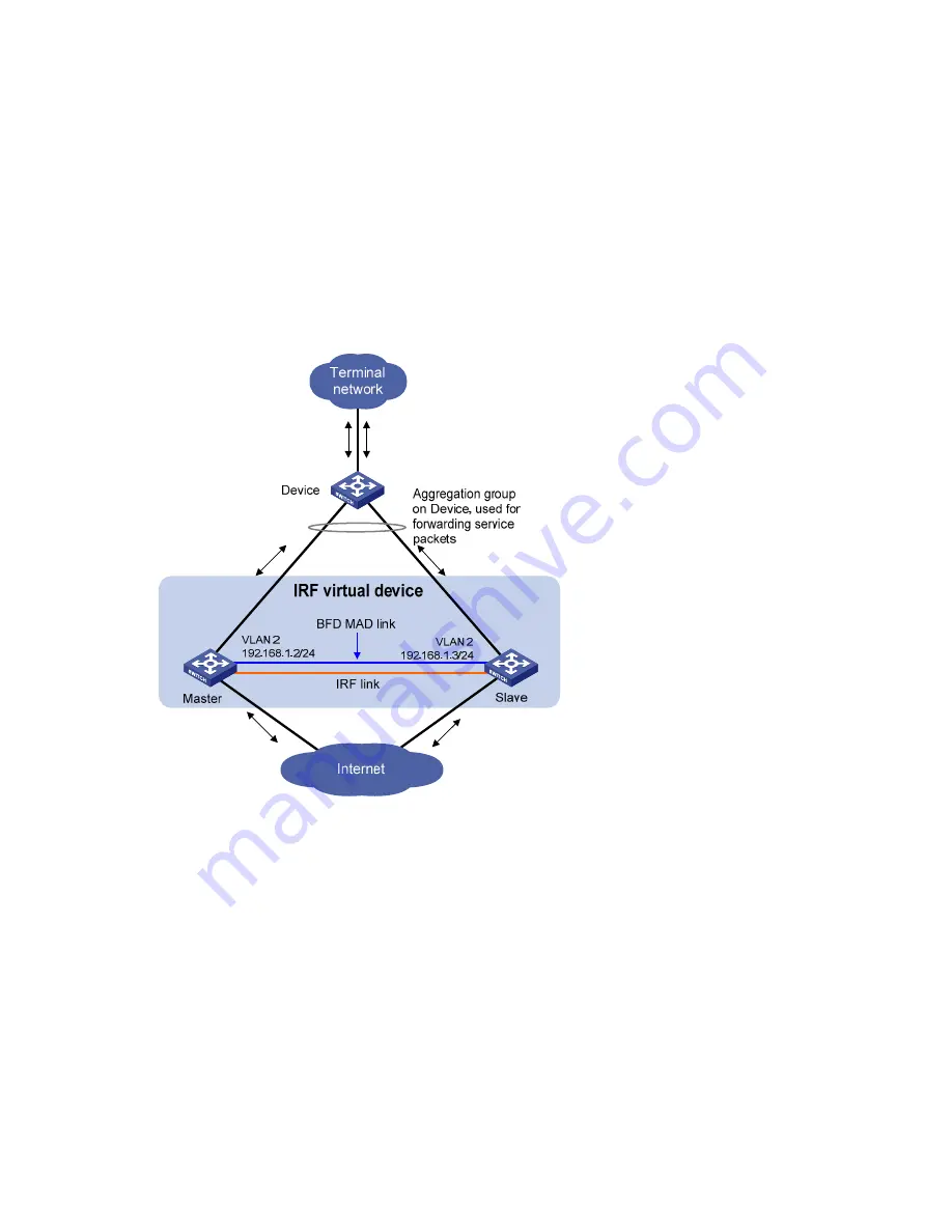
BFD MAD detection can be achieved with or without intermediate devices. In a BFD MAD network 

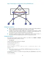
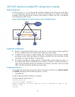
without an intermediate device, connect all IRF member switches with dedicated BFD MAD links in the 
full mesh topology, as shown in 

Figure 9

. The interfaces connected by BFD MAD links must belong to the 

same VLAN. In VLAN interface view, assign different IP addresses on the same network segment for 

different member switches. 

Figure 9


Network diagram for BFD MAD detection 


3.


Configuring BFD MAD detection 

Configure BFD MAD detection by following these steps: 


Create a VLAN dedicated for BFD MAD detection (also required on the intermediate device if any) 


Select the physical IRF ports to be used for BFD MAD detection (at least one on each member 
switch) and add them into the detection-dedicated VLAN (also required on the intermediate device 
if any) 


Create VLAN interfaces for the detection-dedicated VLAN, enable BFD MAD detection on these 
interfaces, and then assign MAD IP addresses for them. 

Содержание A5800 Series

Страница 1: ...procedures These configuration guides also provide configuration examples to help you apply software features to different network scenarios This documentation is intended for network planners field technical support and servicing engineers and network administrators working with the HP A Series products Part number 5998 1626 Software version Release 1211 Document version 5W100 20110430 ...

Страница 2: ...MATERIAL INCLUDING BUT NOT LIMITED TO THE IMPLIED WARRANTIES OF MERCHANTABILITY AND FITNESS FOR A PARTICULAR PURPOSE Hewlett Packard shall not be liable for errors contained herein or for incidental or consequential damages in connection with the furnishing performance or use of this material The only warranties for HP products and services are set forth in the express warranty statements accompan...

Страница 3: ...description for a member switch 15 Configuring load sharing criteria for IRF links 15 Specifying the preservation time of bridge MAC address 17 Enabling automatic boot file updating 18 Setting the IRF link down report delay 19 Configuring MAD detection 19 Configuring LACP MAD 20 Configuring BFD MAD 22 Accessing an IRF virtual device 28 Accessing the master 28 Accessing a slave switch 29 Displaying...

Страница 4: ...virtual device appears as one node on the network Log in at any member switch to manage all members of the IRF virtual device High availability and reliability The member switches in an IRF virtual device work in 1 N redundancy One member switch works as the master to manage and maintain the entire IRF virtual device All other member switches process services as well as back up the master As soon ...

Страница 5: ...vice IP network IRF link Equal to Master Slave IRF topologies Create an IRF virtual device in daisy chain topology or more reliably ring topology as shown in Figure 2 In ring chain topology the failure of one IRF link does not cause the IRF virtual device to split as in daisy chain topology Rather the IRF virtual device changes to a daisy chain topology without affecting network services Figure 2 ...

Страница 6: ...cal IRF port Physical IRF ports are physical copper or fiber ports bound to an IRF port They connect IRF member switches and forward IRF protocol packets and data traffic between IRF member switches For more information about ports that can be used as IRF physical ports on the A5800 and A5820X switches see Connecting the IRF member switches IRF partition IRF partition occurs when an IRF virtual de...

Страница 7: ... at the CLI Connecting the neighbor switches Binding physical ports to IRF ports at the CLI Bind one physical port or for link redundancy multiple physical ports to an IRF port see Configuring IRF ports Table 1 shows the physical ports that can be used as IRF ports and the port use restrictions Table 1 Physical IRF port requirements Switch model Candidate physical IRF ports Requirements A5800 48G ...

Страница 8: ...rface card if installed on the rear panel An IRF port can use physical ports distributed on different cards A5800 24G SFP Switch with 1 Interface Slot JC103A A5800 24G SFP TAA Switch with 1 Interface Slot JG256A The four fixed SFP ports and the ports on the expansion interface card if installed on the front panel A5820X 14XG SFP Switch with 2 Interface Slots JC106A A5820X 14XG SFP TAA Switch with ...

Страница 9: ...or Fiber specifications Maximum transmission distance JD092B HP X130 10G SFP LC SR Transceiver 850 LC 50 125 μm multimode fiber 300 m 984 25 ft 82 m 269 03 ft 66 m 216 54 ft 62 5 125 μm multimode fiber 33 m 108 27 ft 26 m 85 30 ft JD093B HP X130 10G SFP LC LRM Transceiver 1310 LC 62 5 125 μm multimode fiber 220 m 721 78 ft 50 125 μm multimode fiber 220 m 721 78 ft 100 m 328 08 ft JD094B HP X130 10...

Страница 10: ...virtual device is established a new member switch is plugged in the master switch fails or is removed or the partitioned IRF virtual devices merge The master is elected based on the following rules in descending order 1 The current master even if a new member has a higher priority When an IRF virtual device is being formed all member switches consider themselves as the master this rule is skipped ...

Страница 11: ...type trunk For another example on the IRF virtual device Master GigabitEthernet 3 0 1 represents the first fixed port on the front panel of member switch 3 Set its link type to trunk Master system view Master interface gigabitethernet 3 0 1 Master GigabitEthernet3 0 1 port link type trunk File system naming conventions On a standalone switch use the name of storage device to access its file system...

Страница 12: ...member switch When you save the current configuration to the startup configuration file of the master by using the save command all subordinate switches execute the same saving operation This real time configuration synchronization ensures that all the IRF member switches keep the same configuration file If the master fails all the other switches can still operate with the same configuration file ...

Страница 13: ... the IRF virtual device in the recovery state at the CLI to make it take over the active IRF virtual device and protect the services from being affected Then recover the MAD failure For more information about LACP see Layer 2 LAN Switching Configuration Guide For information about BFD see High Availability Configuration Guide For information about gratuitous ARP see Layer 3 IP Services Configurati...

Страница 14: ...an IRF virtual device Accessing the master Required Accessing a slave switch Optional Configuring an IRF virtual device Specifying a domain ID for an IRF virtual device Introduction to IRF domain To differentiate IRF virtual devices each IRF virtual device is assigned a domain ID As shown in Figure 7 Switch A and Switch B form IRF virtual device 1 and Switch C and Switch D form IRF virtual device ...

Страница 15: ...ign domain IDs to them To assign a domain ID to an IRF virtual device To do Use the command Remarks 1 Enter system view system view 2 Assign a domain ID to the IRF virtual device irf domain domain id Required if LACP MAD is adopted Optional if ARP MAD is adopted By default the domain ID of an IRF virtual device is 0 You must assign a domain ID for an IRF virtual device before enabling LACP MAD det...

Страница 16: ...ions such as configuration for physical IRF ports no longer take effect and you will need to configure them again Change the IRF member ID of a switch when it is standalone or after it joins an IRF virtual device If the switch is standalone make sure that the member ID of the switch does not conflict with the member ID of any other switch so the change does not affect the operation of the IRF virt...

Страница 17: ...number 9 Bring up the physical port undo shutdown Required 10 Return to system view quit 11 Save the current configuration save Required 12 Activate the IRF port configuration irf port configuration active Required Bind up to four physical ports to an IRF port for link redundancy and load sharing The physical ports must meet the requirements in Table 1 Before you create or remove an IRF port bindi...

Страница 18: ...cription for a member switch To do Use the command Remarks 1 Enter system view system view 2 Configure a description for a member switch irf member member id description text Optional Not configured by default Configuring load sharing criteria for IRF links Bind multiple physical ports to an IRF port for link redundancy and load sharing You can also configure the switch to distribute traffic acros...

Страница 19: ...00 48G PoE Switch with 1 Interface Slot JC104A and A5800 48G PoE TAA Switch with 1 Interface Slot JG257A base load sharing calculation on the incoming port number Other models in the A5800 and A5820X series use the combination of the source and destination MAC addresses as the load sharing criteria for Layer 2 packets and the combination of the source and destination IP addresses for Layer 3 packe...

Страница 20: ...ce uses bridge MAC address to identify the IRF virtual device by Layer 2 protocols such as MSTP and LACP It uses bridge MAC address for generating an MAC address for a Layer 3 interface As with any other node on a switched LAN this bridge MAC address must be unique for proper communication To avoid duplicate bridge MAC addresses an IRF virtual device can change its bridge MAC address automatically...

Страница 21: ...these steps to upgrade the BootROM 1 Upload the software version file to be used to the master and then use the bootrom upgrade command to upgrade the BootROM of the master 2 Use the boot loader command with the slot all keywords to specify the software version file as the boot file to be used at the next reboot and apply this configuration on all member switches 3 Reboot the all member switches i...

Страница 22: ...n the port does not immediately report the link state changes to the IRF virtual device If the IRF link state is still down when the configured time is reached the port reports the link state changes to the IRF virtual device If the link state changes from down to up the link layer immediately reports the event to the IRF virtual device To set the IRF link down report delay To do Use the command R...

Страница 23: ...received extended LACPDU with its domain ID and active ID If the domain IDs are different the extended LACPDU is from a different IRF virtual device and the switch does not continue to process the extended LACPDU with the MAD mechanism If the domain IDs are the same the switch compares the active IDs If the active IDs are different the IRF virtual device has split If the active IDs are the same th...

Страница 24: ...up of the IRF virtual device used for LACP MAD detection and forwarding services packets 2 Configuring LACP MAD detection Configure LACP MAD detection by following these steps Create an aggregate interface also required on the intermediate device Configure the aggregation group to work in dynamic aggregation mode also required on the intermediate device Enable LACP MAD detection on the dynamic agg...

Страница 25: ...interface interface type interface number 8 Assign the current Ethernet interface to the specified aggregation group port link aggregation group number Required Configuring BFD MAD CAUTION A Layer 3 interface used for BFD MAD must be dedicated Do not configure any other services on a Layer 3 interface with BFD MAD enabled Otherwise both the configured services and the BFD MAD detection function ma...

Страница 26: ...ogy as shown in Figure 9 The interfaces connected by BFD MAD links must belong to the same VLAN In VLAN interface view assign different IP addresses on the same network segment for different member switches Figure 9 Network diagram for BFD MAD detection 3 Configuring BFD MAD detection Configure BFD MAD detection by following these steps Create a VLAN dedicated for BFD MAD detection also required o...

Страница 27: ...he IRF member and the intermediate device to the BFD MAD VLAN the VLAN specific to the BFD MAD enabled VLAN interface A BFD MAD enabled VLAN interface and all ports in the VLAN do not support any Layer 2 and Layer 3 protocol applications including ARP and LACP You cannot enable BFD MAD on VLAN interface 1 Do not bind a BFD MAD enabled Layer 3 interface to any VPN instance The MAD function cannot w...

Страница 28: ...main ID and the active ID in each received extended gratuitous ARP packet with its domain ID and active ID If the domain IDs are different the extended gratuitous ARP packet is from a different IRF virtual device and the switch does not continue to process the packet with the MAD mechanism If the domain IDs are the same the switch compares the active IDs If the active IDs are different the IRF vir...

Страница 29: ... view quit 8 Enter VLAN interface view interface vlan interface number 9 Assign the interface an IP address ip address ip address mask mask length Required No IP address is assigned to any VLAN interface by default 10 Enable ARP MAD mad arp enable Required By default ARP MAD is disabled Excluding a port from the shutdown action on detection of multi active collision By default all service ports of...

Страница 30: ...lly repair the failed links When the link is recovered the IRF virtual device in recovery state automatically reboots Then the IRF virtual devices both in active state and in recovery state automatically merge into one Service ports that were shut down and belonged to the IRF virtual device in recovery state automatically restore their original physical state and the whole IRF virtual device recov...

Страница 31: ...device in one of the following ways Local login Log in through the console port of a member switch Remote login Configure an IP address for a Layer 3 Ethernet interface of a member switch and make sure that the route is reachable and then access the IRF virtual device remotely through Telnet Web or SNMP When you log in to the IRF virtual device actually you log in to the master The master is the c...

Страница 32: ... quit command At that time the master console is reactivated and can output logs To log in to the specified subordinate switch To do Use the command Remarks 1 Enter system view system view 2 Log in to the specified subordinate switch of an IRF virtual device irf switch to member id Required By default you actually log in to the master when you log in to the IRF virtual device Available in user vie...

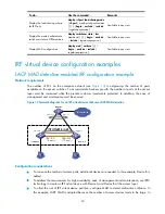
Страница 33: ...is outgrowing the number of ports available on the access switches To accommodate business growth the number of ports at the access layer must be increased while the present customer investments protected In addition the ease of management and maintenance must be ensured Figure 13 Network diagram for an IRF virtual device that uses LACP MAD detection Configuration considerations To increase the nu...

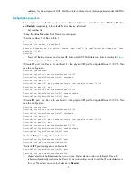
Страница 34: ...group interface ten gigabitethernet 1 0 25 DeviceA irf port1 2 quit DeviceA interface ten gigabitethernet 1 0 25 DeviceA Ten GigabitEthernet1 0 25 undo shutdown DeviceA Ten GigabitEthernet1 0 25 save Create IRF port 1 on Device B and bind it to the physical IRF port Ten GigabitEthernet 2 0 26 Then save the configuration DeviceB system view DeviceB interface ten gigabitethernet 2 0 26 DeviceB Ten G...

Страница 35: ... A and Device B implement MAD detection An LACP supported switch is used here to save the cost Create a dynamic aggregation interface DeviceC system view DeviceC interface bridge aggregation 2 DeviceC Bridge Aggregation2 link aggregation mode dynamic DeviceC Bridge Aggregation2 quit Add ports GigabitEthernet 1 0 1 and GigabitEthernet 1 0 2 to the aggregation interface and they are used for the LAC...

Страница 36: ...e MAD to detect multi active collisions In this example BFD MAD is adopted because the number of member devices is small Configuration procedure This example assumes that the system names of Device A and Device B are DeviceA and DeviceB respectively before the IRF virtual device is formed 1 Set member IDs Keep the default member ID of Device A unchanged Set the member ID of Device B to 2 DeviceB s...

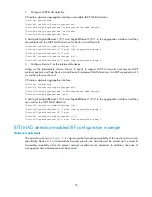
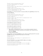
Страница 37: ...tion on Device A DeviceA Ten GigabitEthernet1 0 25 quit DeviceA irf port configuration active Activate IRF port configuration on Device B DeviceB Ten GigabitEthernet2 0 26 quit DeviceB irf port configuration active 3 Master election is held between the two devices As a result of the master election Device B automatically reboots to join the IRF virtual device as a subordinate switch The system nam...

Страница 38: ...aintenance use IRF2 technology to create an IRF virtual device with Device A and Device B at the access layer The IRF virtual device is connected to Device C with dual links To offset the risk of IRF virtual device partition configure MAD to detect multi active collisions In this example ARP MAD is adopted because the number of members in the IRF virtual device is small and the ARP MAD packets are...

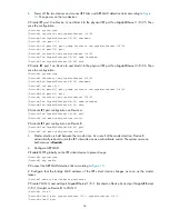
Страница 39: ...2 1 quit DeviceB interface ten gigabitethernet 2 0 26 DeviceB Ten GigabitEthernet2 0 26 undo shutdown DeviceB Ten GigabitEthernet2 0 26 save Activate IRF port configuration on Device A DeviceA Ten GigabitEthernet1 0 25 quit DeviceA irf port configuration active Activate IRF port configuration on Device B DeviceB Ten GigabitEthernet2 0 26 quit DeviceB irf port configuration active 3 Master election...

Страница 40: ... 1 24 DeviceA Vlan interface3 mad arp enable 5 Configure Device C Enable MSTP globally on Device C to prevent loops DeviceC system view DeviceC stp enable Create VLAN 3 and add port GigabitEthernet 1 0 1 and port GigabitEthernet 1 0 2 to VLAN 3 to forward ARP MAD packets DeviceC vlan 3 DeviceC vlan3 port gigabitethernet 1 0 1 gigabitethernet 1 0 2 DeviceC vlan3 quit ...

Страница 41: ... wwalerts After registering you will receive email notification of product enhancements new driver versions firmware updates and other product resources Related information Documents To find related documents browse to the Manuals page of the HP Business Support Center website http www hp com support manuals For related documentation navigate to the Networking section and select a networking categ...

Страница 42: ...parated by vertical bars from which you select one choice multiple choices or none 1 n The argument or keyword and argument combination before the ampersand sign can be entered 1 to n times A line that starts with a pound sign is comments GUI conventions Convention Description Boldface Window names button names field names and menu items are in bold text For example the New User window appears cli...

Страница 43: ...ing capable device such as a router or Layer 3 switch Represents a generic switch such as a Layer 2 or Layer 3 switch or a router that supports Layer 2 forwarding and other Layer 2 features Port numbering in examples The port numbers in this document are for illustration only and might be unavailable on your device ...

Страница 44: ...ent conventions 39 documents and manuals 38 icons used 39 subscription service 38 support contact information 38 symbols used 39 websites 38 icons 39 interface naming conventions 8 IRF application scenario 2 basic concepts 3 benefits 1 configuration 1 establishment of IRF virtual device 4 maintenance of an IRF virtual device 4 operation of IRF virtual device 4 overview 1 topologies 2 virtual devic...

Страница 45: ... setting the IRF link down report delay 19 slave switch 29 specifying a priority for a member switch 15 subscription service 38 support and other resources 38 symbols 39 topology collection 7 websites 38 ...

Отзывы: