Servicing
the
HP
83447A
Replacement
Procedures
Replacing
the
power
supply
Unsolder
the
connections
to
the
dc
power
supply
.
Remove
the
four
screws
that
attach
the
power
supply
to
the
chassis
.
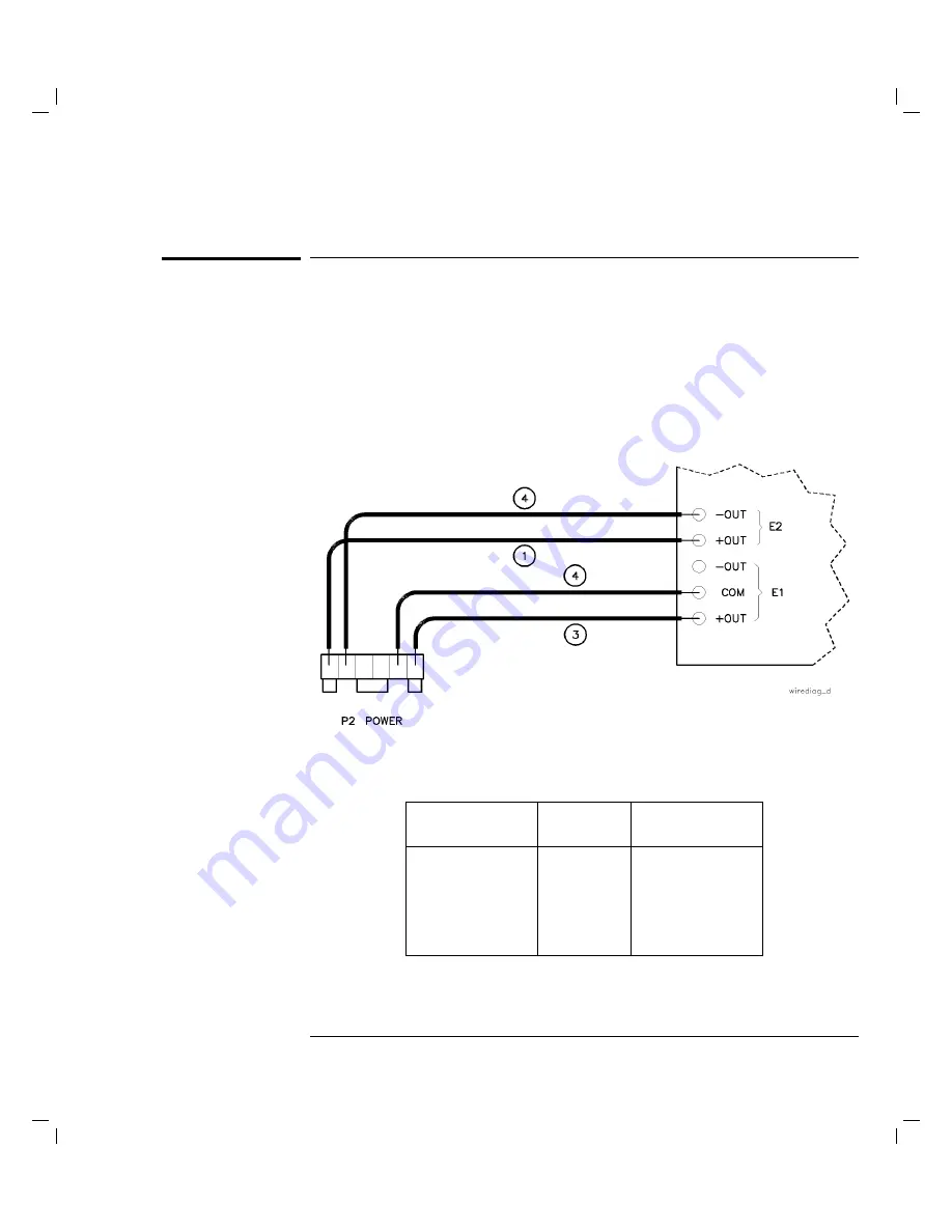
Refer
to
T
able
4-1
,
Figure
4-7
,
T
able
4-9,
and
T
able
4-8
when
installing
a
new
power
supply
.
A
djust
the
5.2
V
and
12
V
power
supplies
to
the
proper
voltages
listed
in
Figure
4-7
.
Figure
4-7.
Wiring
diagram
for
the
power
supply
terminals.
T
able
4-9.
DC
P
ower
Supply
T
erminal
Connections
Index
Number
Cable
A
ttachment
Cable
Color
1
E2
+OUT
black
2
E2
0 OUT
violet
3
E1
+OUT
red
4
E1
COM
black
4-35
Содержание 83447A
Страница 1: ...User and Service Guide HP 83447A Lightwave Trigger Receiver ...
Страница 3: ...Printing History HP Part Number Edition Date 83447 90002 Edition 1 April 1996 iii ...
Страница 10: ......
Страница 15: ...1 General Information ...
Страница 25: ...Declaration of Conformity 1 11 ...
Страница 27: ...General Information Electrostatic Discharge Information Figure 1 3 Example of a static safe work station 1 13 ...
Страница 29: ...2 Installation and Preparation for Use ...
Страница 36: ...Installation and Preparation for Use Installing the HP 83447A Figure 2 3 AC power cables available 2 8 ...
Страница 51: ...3 Using the HP 83447A ...
Страница 55: ...4 Servicing the HP 83447A ...
Страница 93: ...Servicing the HP 83447A Replaceable parts Figure 4 8 HP 83447A assembly level replaceable parts 4 39 ...
Страница 95: ...Servicing the HP 83447A Replaceable parts Figure 4 9 HP 83447A replaceable hardware 4 41 ...
Страница 97: ...Index ...
Страница 102: ...W warranty 2 13 warranty information viii waveform test measuring eye diagram 3 3 Index 6 ...


