UPS installation 41
Configuring the Parallel UPS Card
1.
Unpack the Parallel UPS Card, and be sure that the card was not damaged during shipment.
NOTE:
If installing another X-Slot card, be sure to install the Parallel UPS Card in X-Slot
Communication Bay 2.
2.
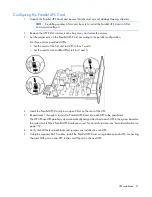
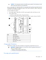
Remove the UPS X-Slot communication bay cover, and retain the screws.
3.
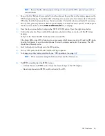
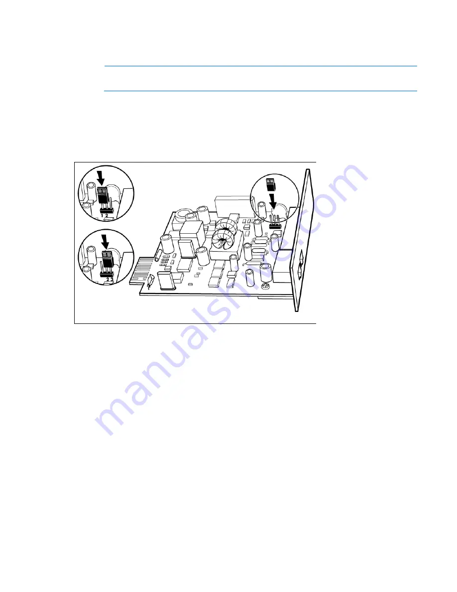
Set the jumper pins on the Parallel UPS Card according to the parallel configuration.
For three or more paralleled UPSs:
o
Set the cards of the first and last UPS to Pins 1 and 2.
o
Set the card for the middle UPS(s) to Pins 2 and 3.
4.
Install the Parallel UPS Card into an open X-Slot on the rear of the UPS.
5.
Repeat steps 1 through 4 to install a Parallel UPS Card into each UPS to be paralleled.
The HP 3 Phase UPS parallel system automatically assigns identities to each UPS in the system based on
the order in which their Parallel UPS Cards are wired. For more information, see "Auto-identification (on
page
)" .
6.
Verify that all the terminal blocks and jumpers are installed in each UPS.
7.
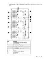
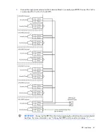
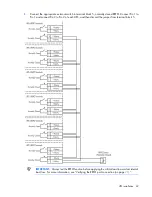
Using the supplied CAT 5 cables, install the Parallel UPS Card wiring between each UPS, connecting
the card OUT port on one UPS to the card IN port on the next UPS.

