background image


Contents  4 

Readying the equipment ................................................................................................................. 56


Installing the mounting rails ...................................................................................................................... 56


Preparing the rails for integrated shipping .................................................................................................. 58


Switching off the UPS battery circuit breaker ............................................................................................... 59


Switching off the ERM circuit breaker ......................................................................................................... 59


Installing the ERM .................................................................................................................................... 60


Attaching the ERM front bezel ......................................................................................................... 62


Connecting the ERM to the UPS ....................................................................................................... 62


Switching on the ERM circuit breaker ............................................................................................... 63


Switching on the UPS battery circuit breaker ..................................................................................... 63


Charging the ERM batteries ............................................................................................................ 63


UPS operations ........................................................................................................................... 64


Mimic screen .......................................................................................................................................... 64


Modes of operation ................................................................................................................................. 64


Standby mode .............................................................................................................................. 64


Normal mode ............................................................................................................................... 65


Battery mode ................................................................................................................................ 66


Auto-Bypass mode ......................................................................................................................... 66


Configuring the UPS ................................................................................................................................ 67


Changing the language.................................................................................................................. 67


Changing display functions ............................................................................................................. 67


Changing user settings ................................................................................................................... 68


Setting the Battery Low alarm level ............................................................................................................. 70


Running automatic battery tests ................................................................................................................. 71


Testing the front panel display ................................................................................................................... 71


Silencing an audible alarm ....................................................................................................................... 71


Verifying the REPO port connection ........................................................................................................... 71


Powering down the standalone UPS ........................................................................................................... 72


Powering down an individual paralleled UPS .............................................................................................. 72


Powering down the parallel system ............................................................................................................ 73


Communication .......................................................................................................................... 74


Installing communication options and control terminals ................................................................................. 74


Communication options ............................................................................................................................ 75


DB-9 communication port................................................................................................................ 75


Control terminals ..................................................................................................................................... 76


Relay output contacts ............................................................................................................................... 76


Programmable signal inputs ...................................................................................................................... 77


Parallel communication ............................................................................................................................ 77


Mode transfers .............................................................................................................................. 78


Redundant signal wiring ................................................................................................................. 78


Auto-identification .......................................................................................................................... 78


Metering ...................................................................................................................................... 79


Power management .................................................................................................................... 80


HP UPS Power Protection Agent overview ................................................................................................... 80


Features ................................................................................................................................................. 80


Maintenance .............................................................................................................................. 81


Removing the UPS front bezel ................................................................................................................... 81


Removing the ERM front bezel ................................................................................................................... 81


Replacing the UPS electronics module ........................................................................................................ 81


Replacing UPS X-Slot cards ....................................................................................................................... 83


Configuring the Parallel UPS Card ............................................................................................................. 84


Содержание 3 Phase SERIES

Страница 1: ...nformation for the HP 3 Phase UPS This document is for the person who installs and maintains power products HP assumes you are qualified in the servicing of high voltage equipment and trained in recognizing hazards in products with hazardous energy levels Part Number 435256 004 January 2013 Edition 4 ...

Страница 2: ...e without notice The only warranties for HP products and services are set forth in the express warranty statements accompanying such products and services Nothing herein should be construed as constituting an additional warranty HP shall not be liable for technical or editorial errors or omissions contained herein ...

Страница 3: ...ting the UPS to utility power 23 Switching on the UPS battery circuit breaker 24 Connecting devices to the UPS 24 Charging the UPS batteries 25 Powering up the standalone UPS 25 Installing in a parallel configuration 26 Installing the input and output wiring 26 Wiring the terminal block 28 Connecting the ground bonding cable 29 Connecting the REPO port 30 Connecting the UPSs to the Bus Bar 35 Swit...

Страница 4: ... Battery Low alarm level 70 Running automatic battery tests 71 Testing the front panel display 71 Silencing an audible alarm 71 Verifying the REPO port connection 71 Powering down the standalone UPS 72 Powering down an individual paralleled UPS 72 Powering down the parallel system 73 Communication 74 Installing communication options and control terminals 74 Communication options 75 DB 9 communicat...

Страница 5: ...rror and UPS does not start 97 Phase rotation verification 97 Power is not available at the UPS output receptacle 97 Protected equipment is not on 98 Overload condition 98 Overtemperature condition 98 Redundancy loss due to overload 98 Selective trip 99 Site wiring condition 99 UPS detects software incompatibility 99 UPS does not power down 99 UPS does not power up 99 UPS does not provide the expe...

Страница 6: ...iance 108 Turkey RoHS material content declaration 108 Ukraine RoHS material content declaration 108 Warranty information 108 Limited warranty 108 250 000 Computer Load Protection Guarantee 108 Pre Failure Battery Warranty 109 Electrostatic discharge 110 Preventing electrostatic discharge 110 Grounding methods to prevent electrostatic discharge 110 Acronyms and abbreviations 111 Documentation feed...

Страница 7: ... UPS Card in each paralleled UPS provides connectivity for system metering and operational mode control In a parallel system not fully loaded the system will shift load to UPSs with the strongest batteries or additional ERMs to maximize runtime when on battery Parallel systems can be configured for capacity or redundancy 6U UPS height 3U ERM height Normal operating mode that minimizes heat generat...

Страница 8: ...andalone UPS directly below the UPS or with rack side panels removed in an adjacent rack to the left of the rack containing the UPS Mount ERMs for a parallel system in an adjacent rack to the left of the rack containing the UPSs rack side panels removed For consistent runtimes each UPS in a parallel system should have the same number of ERMs Some load equipment may require phase rotation or phase ...

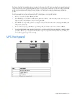
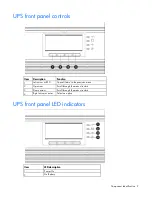
Страница 9: ...Function 1 Left arrow or ESC Cancel return to the previous menu 2 Up arrow Scroll through the menu structure 3 Down arrow Scroll through the menu structure 4 Right arrow or enter Select an option UPS front panel LED indicators Item LED description 1 Power On 2 On Battery ...

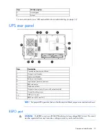
Страница 10: ...rcuit breaker 5 Input output power connectors 6 ERM connector 7 Option card slots 8 Output connector only for use with output module 9 Ground bonding screw 10 DB 9 service port 11 REPO port NO and NC NOTE For proper UPS operation be sure that the terminal block jumpers are inserted as shown REPO port WARNING The REPO circuit is an IEC 60950 safety extra low voltage SELV circuit This circuit must b...

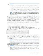
Страница 11: ...e that removes the AC source from the input of the UPS When the switch is activated The REPO feature immediately powers down protected devices and does not utilize the orderly shutdown procedure initiated by power management software The REPO feature shuts down UPS units operating under either utility or battery power Keep the REPO connector installed in the REPO port on the UPS even if the REPO f...

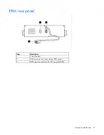
Страница 12: ...Component identification 12 ERM rear panel Item Description 1 Circuit breaker 2 ERM input connector from another ERM output 3 ERM output connector to the UPS or another ERM ...

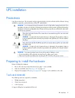
Страница 13: ...al material handling 77 kg 170 lb This symbol indicates that the ERM exceeds the recommended weight for one individual to handle safely WARNING To reduce the risk of personal injury or damage to the equipment observe local occupational health and safety requirements and guidelines for manual material handling WARNING To prevent personal injury from earth conductor leakage current Do not operate th...

Страница 14: ...ch circuit such as the use of power strips Electrical requirements All models require a dedicated unshared branch circuit suitably rated for the specific UPS as stated in Input specifications Readying the equipment 1 Check the battery recharge date specified on the label that is affixed to the shipping carton IMPORTANT Do not use the battery if the recharge date has passed If the date on the batte...

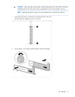
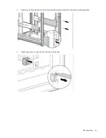
Страница 15: ...m first and continue to populate the rack from the bottom to the top NOTE Mounting hardware for square and round holed racks is included in the UPS kit 1 Select the proper holes in the rack for positioning the UPS in the rack The UPS rails are installed in positions 1 and 12 2 Loosen the hex nuts and extend the brackets to the desired length ...

Страница 16: ...UPS installation 16 3 Insert screws through the rack into the mounting rail and the front of each mounting bracket 4 Install cage nuts or clip nuts into the rear of the rack ...

Страница 17: ...l the rear mounting brackets Installing the UPS Before installing the UPS review and observe all warnings in Precautions on page 13 WARNING A risk of personal injury or damage to the equipment exists Uneven loading of equipment in the rack might cause the rack to become unstable Install the heavier components first and then continue to populate the rack from the bottom to the top ...

Страница 18: ...ng rails on page 14 2 With one person on each side of the carton lift the chassis and lower it to the floor in front of the rack 3 Install the mounting ears on the chassis using the screws provided 4 With one person on each side lift the chassis to rail level and slide the chassis on the mounting rails 5 Attach the chassis to the rack using the supplied screws 6 If using the rear mounting brackets...

Страница 19: ... all circuit breakers on the rear panel of the UPS are in the Off position Installing the batteries WARNING To prevent personal injury prepare the area and observe all materials handling procedures when transporting a battery module Battery modules weigh 20 kg 44 lb ...

Страница 20: ...to the electronics module 2 Attach the UPS front bezel Connecting the ground bonding cable The ground bonding screw is provided as an attachment point for conductors Use a ground bonding cable if the rack contains any conductors for the purpose of functional grounding or bonding of ungrounded metal parts ...

Страница 21: ... to a REPO circuit NOTE Wire the connector block using stranded nonshielded wire AWG 22 18 or equivalent HP recommends using different colors for the positive and negative wires To avoid inadvertant EPO Minimize wire strain while connecting the REPO port Avoid allowing the wires to hang in the rear of the UPS Use tie wraps and tie wrap blocks to secure the wires tightly to the rack and the rear of...

Страница 22: ...e appropriate external switch to terminal block 4 normally open REPO IMPORTANT Always test the REPO function before applying the critical load to avoid accidental load loss For more information see Verifying the REPO port connection on page 71 4 Reconnect terminal block 4 normally open REPO and then power on the UPS manually to restart Pins should remain open to keep the UPS running Maximum resist...

Страница 23: ...unction before applying the critical load to avoid accidental load loss For more information see Verifying the REPO port connection on page 71 4 Reconnect terminal block 5 normally closed REPO and then power on the UPS manually to restart The pins must be shorted to keep the UPS running Maximum resistance is 10 ohm Connecting the UPS to utility power WARNING To prevent injury from electric shock o...

Страница 24: ...s current drawn by this type of printer can overload the UPS Before connecting devices verify that the UPS will not overload by checking that the ratings of the devices do not exceed the UPS capacity If the equipment rating is listed in amps multiply the number of amps by the nominal AC source to determine the VA To provide additional receptacles For the 8kVA models Plug a PDU into the UPS output ...

Страница 25: ...er to devices The batteries charge to 80 percent of their capacity within 5 hours 100 percent of their capacity within 48 hours Powering up the standalone UPS NOTE Be sure that the total equipment ratings do not exceed the UPS capacity to prevent an overload alarm 1 Switch the UPS input circuit breaker to the On position 2 Wait for the UPS front panel display to illuminate The Alarm LED flashes 3 ...

Страница 26: ...tart if necessary The UPS should be in Operate mode 9 Switch the output circuit breaker to the On position 10 To return to the default logo screen press the ESC button Installing in a parallel configuration WARNING This equipment must be installed by a licensed electrician or trained service personnel familiar with high power circuitry A UPS connected to a Bus Bar with a paralleling line cord is i...

Страница 27: ...he cover back and off the wireway and retain 4 Remove the six screws on the conduit landing plate and retain 5 Remove the plate and retain 6 Use a Greenlee punch to provide one or more holes in the conduit landing plate to accommodate the input and output wiring from the utility to the Power Bus Bar 7 Replace the conduit landing plate 8 Reinstall the UPS above the wireway ...

Страница 28: ...ans connectors breakers or X Slot cards on any HP 3 Phase UPS See the wireway label Wiring the terminal block Connect the input output and ground wires to the Power Bus Bar terminal block Route the three input phases and the input neutral through the ferrite assembly Wire gauge depends on overcurrent protection rating required For more information see Installing in a parallel configuration on page...

Страница 29: ...2 350 kcmil 31 1 Nm 275 lb in 6 Phase 3 in 13 3 mm2 6 AWG to 177 mm2 350 kcmil 31 1 Nm 275 lb in Neutral 7 Neutral 13 3 mm2 6 AWG to 177 mm2 350 kcmil 31 1 Nm 275 lb in 8 Neutral 13 3 mm2 6 AWG to 177 mm2 350 kcmil 31 1 Nm 275 lb in 9 Neutral 13 3 mm2 6 AWG to 177 mm2 350 kcmil 31 1 Nm 275 lb in Safety ground 10 Ground 18 mm2 4 AWG to 215mm2 400 kcmil 1 8 16 lb in Use 13 3 mm2 6 AWG 90º C copper w...

Страница 30: ... to a REPO circuit NOTE Wire the connector block using stranded nonshielded wire AWG 22 18 or equivalent HP recommends using different colors for the positive and negative wires To avoid inadvertant EPO Minimize wire strain while connecting the REPO port Avoid allowing the wires to hang in the rear of the UPS Use tie wraps and tie wrap blocks to secure the wires tightly to the rack and the rear of...

Страница 31: ... must be in parallel To install a REPO switch for a parallel system 1 Verify that the UPS system is powered down and all power sources are removed For more information see Powering down the parallel system on page 73 2 Mount the remote REPO switch HP recommends mounting the REPO switch near the operator s consoles or near the exit doors For enclosure dimensions and wiring knockouts see the REPO sw...

Страница 32: ...minal block 4 normally open REPO Connect Pin 1 to Pin 1 and connect Pin 2 to Pin 2 of each UPS IMPORTANT Always test the REPO function before applying the critical load to avoid accidental load loss For more information see Verifying the REPO port connection on page 71 ...

Страница 33: ... the entire parallel system using a single switch To install a REPO switch for a parallel system the selected REPO command NO or NC contacts from each UPS in the system must be in parallel To install a REPO switch for a parallel system 1 Verify that the UPS system is powered down and all power sources are removed For more information see Powering down the parallel system on page 73 2 Mount the rem...

Страница 34: ...sed REPO Connect Pin 1 to Pin 1 and connect Pin 2 to Pin 2 of each UPS and then discard the jumper from terminal block 5 IMPORTANT Always test the REPO function before applying the critical load to avoid accidental load loss For more information see Verifying the REPO port connection on page 71 ...

Страница 35: ...ing the UPSs to the Bus Bar To connect the parallel input cord from each paralleled UPS to the Bus Bar in the rack 1 Gently loop and twist the parallel input cords to minimize stress on the cords The loop and twist for each cord might vary depending on configuration and strain relief 2 Pull the cord retention bracket away from the Bus Bar 1 3 Connect the parallel input cord to the Bus Bar 2 ...

Страница 36: ...UPS installation 36 4 Secure the parallel input cord by pushing in the cord retention bracket 3 ...

Страница 37: ...n each UPS 3 Check each UPS front panel display for active alarms or notices other than Batteries Disconnected Resolve any active alarms before continuing For alarm troubleshooting see LED and audible alarm troubleshooting on page 94 Switching on the UPS battery circuit breaker When the UPS is plugged in and the battery circuit breaker is on the UPS automatically enters Standby mode and begins cha...

Страница 38: ...g a PDU into the UPS output receptacle at the end of the power cord For the 12kVA models a Install the included output module on the rear rack frame b Plug the output module into the special UPS output receptacle located on the rear of the UPS Item Description 1 Rack corner post 2 Mounting locations 3 Mounting top bracket 4 Output cord 5 Mounting bottom bracket 6 Input cord Charging the UPS batter...

Страница 39: ...he front panel to view the active alarms Correct the alarms and restart if necessary The UPS should be in Normal mode 5 Switch all output circuit breakers to the ON position 6 On any UPS press the ESC button until the HP logo appears 7 To change any other factory set defaults see UPS operations on page 64 NOTE HP recommends setting the Date and Time and the Start screen 8 If a REPO is installed te...

Страница 40: ...e rack from the bottom to the top 1 Install the mounting rails Installing the mounting rails on page 56 Installing the mounting rails on page 14 2 With one person on each side of the carton lift the chassis and lower it to the floor in front of the rack 3 Install the mounting ears on the chassis using the screws provided 4 With one person on each side lift the chassis to rail level and slide the c...

Страница 41: ...S to Pins 1 and 2 o Set the card for the middle UPS s to Pins 2 and 3 4 Install the Parallel UPS Card into an open X Slot on the rear of the UPS 5 Repeat steps 1 through 4 to install a Parallel UPS Card into each UPS to be paralleled The HP 3 Phase UPS parallel system automatically assigns identities to each UPS in the system based on the order in which their Parallel UPS Cards are wired For more ...

Страница 42: ...and so on Item Description 1 Standalone parallel terminal block removed 2 For parallel use only 3 Redundant signal cable 4 Standalone parallel terminal block 5 For parallel use only 6 Standalone parallel terminal block 7 UPS UNIT 1 8 UPS UNIT 2 9 Parallel UPS Card cable with ferrite 10 CAN OUT port 11 CAN IN port ...

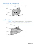
Страница 43: ...rate normally For example when shutting down one UPS the remaining UPS transfers the load to bypass instead of supporting the load Be sure all wiring is correct for proper operation 10 Remove the Standalone Parallel terminal block connector from the top UPS 11 Tighten the screws securing each Parallel UPS Card in the X Slot communication bay Removing the UPS battery bracket Be sure that all circui...

Страница 44: ...UPS installation 44 Replacing the UPS battery bracket Attaching the UPS front bezel 1 Connect the cable to the electronics module ...

Страница 45: ...tors for the purpose of functional grounding or bonding of ungrounded metal parts The ground bonding cable is not included Connecting the REPO port This UPS has two REPO ports normally open and normally closed Before connecting to a REPO port review and observe all warnings WARNING The pins on the REPO port are polarity sensitive Be sure to verify polarity while connecting the REPO port in paralle...

Страница 46: ...g the REPO connection see Verifying the REPO port connection on page 71 Connecting to a normally open contact IMPORTANT The remote switch must be in the open position to enable power to the UPS output You can install an optional REPO circuit that shuts down the entire parallel system using a single switch To install a REPO switch for a parallel system the selected REPO command NO or NC contacts fr...

Страница 47: ...minal block 4 normally open REPO Connect Pin 1 to Pin 1 and connect Pin 2 to Pin 2 of each UPS IMPORTANT Always test the REPO function before applying the critical load to avoid accidental load loss For more information see Verifying the REPO port connection on page 71 ...

Страница 48: ... the entire parallel system using a single switch To install a REPO switch for a parallel system the selected REPO command NO or NC contacts from each UPS in the system must be in parallel To install a REPO switch for a parallel system 1 Verify that the UPS system is powered down and all power sources are removed For more information see Powering down the parallel system on page 73 2 Mount the rem...

Страница 49: ...sed REPO Connect Pin 1 to Pin 1 and connect Pin 2 to Pin 2 of each UPS and then discard the jumper from terminal block 5 IMPORTANT Always test the REPO function before applying the critical load to avoid accidental load loss For more information see Verifying the REPO port connection on page 71 ...

Страница 50: ...ing the UPSs to the Bus Bar To connect the parallel input cord from each paralleled UPS to the Bus Bar in the rack 1 Gently loop and twist the parallel input cords to minimize stress on the cords The loop and twist for each cord might vary depending on configuration and strain relief 2 Pull the cord retention bracket away from the Bus Bar 1 3 Connect the parallel input cord to the Bus Bar 2 ...

Страница 51: ...from electric shock or damage to the equipment Plug the input line cord into a grounded earthed electrical outlet that is installed near the equipment and is easily accessible Do not disable the grounding plug on the input line cord The grounding plug is an important safety feature Do not use extension cords Connect the UPS to a grounded utility power outlet ...

Страница 52: ...eck each UPS front panel display for active alarms or notices other than Batteries Disconnected Resolve any active alarms before continuing For alarm troubleshooting see LED and audible alarm troubleshooting on page 94 Switching on the UPS battery circuit breaker When the UPS is plugged in and the battery circuit breaker is on the UPS automatically enters Standby mode and begins charging the batte...

Страница 53: ...eptacle at the end of the power cord For the 12kVA models a Install the included output module on the rear rack frame b Plug the output module into the special UPS output receptacle located on the rear of the UPS Item Description 1 Rack corner post 2 Mounting locations 3 Mounting top bracket 4 Output cord 5 Mounting bottom bracket 6 Input cord Charging the UPS batteries With the UPS in Standby mod...

Страница 54: ...Press the right arrow button 4 Confirm the selection Press and hold the right arrow button for three seconds until the UPS stops beeping Verify that the Power On LED illuminates solid on each UPS If the Alarm LED on any UPS is flashing do not proceed until all alarms are clear Check the UPS status from the front panel to view the active alarms Correct the alarms and restart if necessary The UPS sh...

Страница 55: ... operating ambient temperature of the rack environment might be greater than room ambient temperature Install the equipment in an environment compatible with the operating temperature Environmental specifications on page 103 Reduced air flow In the rack the rate of air flow required for safe operation of the equipment must not be compromised Circuit overloading Consideration should be given to the...

Страница 56: ...it will be assembled Installing the mounting rails WARNING To reduce the risk of personal injury or damage to the equipment be sure that The leveling feet are extended to the floor The full weight of the rack rests on the leveling feet The stabilizing feet are attached to the rack if it is a single rack installation The racks are coupled together in multiple rack installations Only one component i...

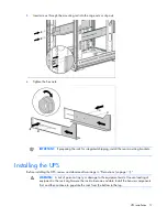
Страница 57: ...ERM installation 57 2 Insert screws through the rack into the mounting rail and the front of each mounting bracket 3 Install cage nuts or clip nuts into the rear of the rack ...

Страница 58: ...he wing nuts or hex nuts Preparing the rails for integrated shipping If the unit is to be shipped in a rack 1 Remove the hex nuts from the mounting rail 2 Install the rail reinforcement plates and tighten using the hex nuts with captive washers included in the kit instead of the nuts included with the rail ...

Страница 59: ...UPS battery circuit breaker WARNING To prevent the UPS from dropping the load be sure to switch off only the UPS battery circuit breaker Once the battery circuit breaker is switched off an audible alarm sounds the Alarm LED flashes and the LCD displays Battery not connected To silence an audible alarm see Silencing an audible alarm on page 71 Switching off the ERM circuit breaker ...

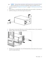
Страница 60: ...the rack might cause the rack to become unstable Install the heavier components first and then continue to populate the rack from the bottom to the top CAUTION Always plan the rack installation so that the heaviest item is on the bottom of the rack Install the heaviest item first and continue to populate the rack from the bottom to the top 1 Install the mounting rails Installing the mounting rails...

Страница 61: ...the mounting rails 5 Attach the chassis to the rack using the supplied screws 6 If using the rear mounting brackets be sure that the bracket tabs are fully inserted into the rear panel cutouts then tighten the brackets The UPS auto detects ERM installation by updating the system runtime If the system runtime is not updated verify installation or see Troubleshooting on page 94 ...

Страница 62: ...tion 62 Attaching the ERM front bezel Connecting the ERM to the UPS NOTE To install a second ERM plug the cable from the second ERM into the socket at the rear of the first ERM Up to four ERM units can be connected ...

Страница 63: ...UPS automatically enters Standby mode and begins charging the batteries Charging the ERM batteries Connect the UPS to a grounded utility power outlet When the UPS is plugged in it automatically enters Standby mode and begins charging the ERM batteries With the UPS in Standby mode allow the ERM batteries to charge for at least 24 hours before putting the UPS into service ...

Страница 64: ...es of operation The UPS has four modes of operation Standby mode on page 64 Normal mode on page 65 Battery mode on page 66 Auto Bypass mode on page 66 Standby mode In Standby mode No power is available at the UPS output receptacles The UPS charges the batteries as necessary The UPS can be placed in Standby mode when the UPS is in Normal mode on page 65 To place the UPS in Standby mode 1 Power down...

Страница 65: ...xceeds normal operating range the UPS transfers to Standard mode Online mode to produce a regulated output voltage When the input line returns to normal operating range the UPS returns to High Efficiency mode on page 65 Full Time Standard mode Full Time Standard mode continuous Online mode is user selectable for full time operation High Efficiency mode By default the UPS operates in a High Efficie...

Страница 66: ...e electronics module s being replaced The UPS detects that the control panel is disconnected from the electronics module The UPS detects an internal failure The UPS detects an overtemperature condition The UPS has an overload condition For more information about the conditions that put the UPS into Auto Bypass mode see Troubleshooting on page 94 To place the UPS in Auto Bypass mode 1 Verify that a...

Страница 67: ... ERMS are used in a parallel system Each UPS must have its own ERM Each UPS must have the same number of ERMs per UPS to ensure consistent runtimes NOTE Standalone and parallel UPSs automatically detect the number of ERMs connected Changing the language Press and hold the far left button for approximately five seconds to select the language menu This action is possible from any LCD menu screen Cha...

Страница 68: ... When this command is active the option changes to Go to Normal mode Start Battery Test Schedules a battery test The battery test might not start immediately Display Test Four different selectable tests for the front panel functions The LEDs cycle through The alarm sounds The backlight turns off and on The pixels scroll through to test the LCD Settings User Settings For more information see Changi...

Страница 69: ...tification For more information see Auto identification on page 78 None Battery Setup Number of ERMs 0 through 4 For more information see Configuring the UPS on page 67 0 internal batteries only Battery Low Alarm Level 1 750 through 1 950 volts per cell 1 880 V cell Automatic Battery Tests Enabled Disabled Enabled automatically runs the battery test once a month Enabled Power Strategy High Efficie...

Страница 70: ...ETTINGS BATTERY SETUP Automatic Battery Tests 3 Use the up or down arrow buttons to select the volts per cell For a list of settings see the table below 4 Press the left arrow button to save the setting 5 Press and hold the ESC button until the Start screen appears Warning time in minutes Number of ERMs installed Battery Low Alarm Level user setting 20 Load 50 Load 100 Load 2 1 1 783 1 821 1 854 2...

Страница 71: ...r down arrow buttons to select Disabled 4 Press the left arrow button to save the setting 5 Press and hold the ESC button until the Start screen appears Testing the front panel display To test the LEDs 1 Press any button to activate the menu options 2 Select CONTROL DISPLAY TEST 3 Confirm the selection by pressing the right arrow button Press ESC to stop the test Silencing an audible alarm To sile...

Страница 72: ... for three seconds until the UPS stops beeping The output relays open the UPS transfers to Standby mode on page 64 and the Power On LED turns off 5 Switch the UPS battery circuit breaker to the Off position 6 If optional ERMs are installed switch all ERM battery circuit breakers to the Off position 7 Switch the UPS input circuit breaker to the Off position 8 Press ESC until the HP logo appears 9 D...

Страница 73: ...t the TURN UPS ON OFF TURN SYSTEM OFF and press the right arrow button 4 Confirm the selection Press and hold the right arrow button for three seconds until the UPS stops beeping The UPS removes power to the parallel UPS system output The output relays open the UPS transfers to Standby mode and the Power On LED turns off 5 Switch the UPS battery circuit breaker to the Off position 6 If optional ER...

Страница 74: ...undant signal wiring for parallel use only 8 Relay output contacts 9 Option card bay 1 10 Option card bay 2 To install the communication options and control terminals 1 Install the appropriate option card and or necessary cable s 2 Connect the cables to the appropriate locations For detailed information see Communication options on page 75 or Control terminals on page 76 3 Route and tie the cable ...

Страница 75: ... front panel menus X Slot 1 independent X Slot 2 multiplexed DB 9 communication port multiplexed HP UPS Management Module HP Parallel UPS Card Available HP UPS Management Module Not in use Available DB 9 communication port To establish communication between the UPS and a computer connect the computer to the UPS communication port using the supplied communication cable For the communication port lo...

Страница 76: ...inals have a functional isolation from terminal to terminal They are connected to the UPS chassis through individual 1 MW resistors If using a semiconductor switch type pay attention to the proper polarity A relay or other mechanical control is preferred Relay output contacts WARNING The relay output contacts must not be connected to any utility connected circuits Reinforced insulation to the util...

Страница 77: ...ion regardless of the bypass status 1 on OFF If active the UPS output powers down regardless of the mode of operation Auxiliary power communication and rectifier battery charger remain functional Restart is initiated immediately when the signal is inactive 2 charger off If active the battery charge function is disabled In a utility power outage the discharge of batteries is supported 2 1 Program f...

Страница 78: ...PS can transfer to Battery mode on page 66 as necessary If any UPS must transfer to Auto Bypass mode on page 66 the redundant signal wiring allows the entire parallel system to transfer to Auto Bypass mode without backfeeding Auto identification The UPS parallel system automatically assigns identities to each UPS in the system To take advantage of this feature wire the Parallel UPS Cards together ...

Страница 79: ...or example in a two unit parallel system with one Anderson load connection for 12 kVA the Load Receptacle current would read 12 kVA on one UPS and zero on the other UPS but the Output measurement would be 6 kVA on each UPS half the total In a standalone UPS the load can be connected from the outlet cord or the Anderson load connector The Output measurement would be the total load on the UPS and th...

Страница 80: ...ment during a utility power failure For UPSs with multiple load segments the management module manages independent UPS load segments to provide separate power control of connected equipment NOTE The HP 3 Phase UPSs have only one load segment Prioritizes the timing of equipment shutdown and reboots connected equipment by load segment Delays restart by load segment after a power outage to sequence t...

Страница 81: ...Maintenance 81 Maintenance Removing the UPS front bezel Removing the ERM front bezel Replacing the UPS electronics module ...

Страница 82: ...pass mode on page 66 o Parallel for redundancy configuration No mode transfer is necessary If the UPS is operating in a parallel for redundancy configuration when the electronics module is replaces the load automatically transfers to the remaining UPSs NOTE Disconnecting the control panel from the electronics module automatically transfers the UPS to Auto Bypass mode However HP recommends transfer...

Страница 83: ... be replaced without powering down the UPS 1 optional To replace the component with the UPS powered down do one of the following o Standalone UPS configuration See Powering down the standalone UPS on page 72 o Individual UPS in a parallel configuration See Powering down an individual paralleled UPS on page 72 o Parallel UPS configuration See Powering down the parallel system on page 73 2 Disconnec...

Страница 84: ...he Parallel UPS Card 1 Unpack the Parallel UPS Card and be sure that the card was not damaged during shipment NOTE If installing another X Slot card be sure to install the Parallel UPS Card in X Slot Communication Bay 2 2 Remove the UPS X Slot communication bay cover and retain the screws 3 Set the jumper pins on the Parallel UPS Card according to the parallel configuration For three or more paral...

Страница 85: ...hase UPS parallel system automatically assigns identities to each UPS in the system based on the order in which their Parallel UPS Cards are wired For more information see Auto identification on page 78 6 Verify that all the terminal blocks and jumpers are installed in each UPS 7 Using the supplied CAT 5 cables install the Parallel UPS Card wiring between each UPS connecting the card OUT port on o...

Страница 86: ...d so on Item Description 1 Standalone parallel terminal block removed 2 For parallel use only 3 Redundant signal cable 4 Standalone parallel terminal block 5 For parallel use only 6 Standalone parallel terminal block 7 UPS UNIT 1 8 UPS UNIT 2 9 Parallel UPS Card cable with ferrite 10 CAN OUT port 11 CAN IN port ...

Страница 87: ...on page 87 and Battery care and storage guidelines on page 87 2 Follow the instructions in UPS battery replacement procedure on page 88 Important battery safety information WARNING The unit contains sealed lead acid battery modules To prevent fire or chemical burns Do not attempt to recharge batteries after removal from the unit Do not disassemble crush or puncture the batteries Do not short the e...

Страница 88: ...le and can be replaced without powering down the UPS 1 optional To replace the component with the UPS powered down do one of the following o Standalone UPS configuration See Powering down the standalone UPS on page 72 o Individual UPS in a parallel configuration See Powering down an individual paralleled UPS on page 72 o Parallel UPS configuration See Powering down the parallel system on page 73 C...

Страница 89: ...the battery test NOTE For an accurate battery test test the UPS with at least 10 load applied to the UPS To test a new battery module 1 Plug the UPS into a power outlet for 48 hours to charge the battery 2 Press any button to activate the menu options Select CONTROL and then START BATTERY TEST During the battery test the front panel displays Battery Test Pending A failed battery test initiates a B...

Страница 90: ...ord 6 Disconnect the communications cable from the option card 7 Disconnect the ground bonding cable 8 Disconnect the REPO port 9 Unplug the load devices 10 Unplug all connected extension bars and PDUs 11 Unplug the ERM connected to the UPS 12 Remove the UPS front bezel Removing the UPS front bezel on page 81 13 Remove the UPS battery bracket Removing the UPS battery bracket on page 19 14 Remove t...

Страница 91: ...nding on your system configuration a driver download might be required to successfully install the converter The driver can be downloaded from the USB Drivers website http www usb drivers com drivers 123 123294 htm To configure a USB port to the COM 1 port on systems that do not have available serial ports 1 Connect the USB to serial converter to the USB port on your system 2 For Windows Vista cli...

Страница 92: ...heckbox is selected For Windows XP the USB settings might be different Choose the lowest most dependable Receive and Transmit buffers by using the list menus radio buttons or other selection methods 13 Click OK to close the Advanced screen 14 Click OK to close the Device Manager screen 15 Run the firmware Flash batch file program Follow the instructions provided with the program Reassigning the US...

Страница 93: ...Maintenance 93 a Click Action The Action Menu appears b Click Scan for hardware changes to refresh the screen and display the changes ...

Страница 94: ...s any button on the front panel display to activate the menu options 2 Press the down arrow button until EVENT LOG displays 3 Press the right arrow button to display the list of alarms and conditions Alarm LED On Battery LED Power On LED Auto Bypass LED Audible alarm Condition On UPS is in Normal mode on page 65 Flashing A new message is active On On 1 beep every 5 seconds On Battery UPS is on bat...

Страница 95: ...onditions see LED and audible alarm troubleshooting on page 94 Abnormal output voltage at startup Possible cause The system is not configured as parallel Action 1 Verify the Parallel UPS Card wiring connections See Configuring the Parallel UPS Card on page 41 2 Be sure that the line cord is installed properly 3 Power down the UPS where the alarm is indicated o Standalone UPS configuration See Powe...

Страница 96: ...attery Low warning might occur before the batteries reach 25 capacity For battery runtime information see Battery runtimes on page 104 When utility power is restored the UPS restarts automatically provides power to the load and charges the battery Battery test condition Action Battery test pending 1 Wait until the test completes 2 See Testing the new battery module on page 89 Battery test did not ...

Страница 97: ...ion persists contact an HP authorized service representative Configuration error and UPS does not start Possible cause The UPS failed to identify itself as a paralleled UPS within two minutes after utility power was applied Action 1 Verify the Parallel UPS Card wiring connections See Configuring the Parallel UPS Card on page 41 2 If the condition persists contact an HP authorized service represent...

Страница 98: ...Bypass mode on page 66 if the load increases The alarm resets when the conditions becomes inactive Overtemperature condition Possible cause The UPS internal temperature is too high or a fan has failed Action 1 Power down the UPS o Standalone UPS configuration See Powering down the standalone UPS on page 72 o Individual UPS in a parallel configuration See Powering down an individual paralleled UPS ...

Страница 99: ...stem have the same firmware version To update the firmware see Updating the UPS firmware on page 91 UPS does not power down Possible cause The batteries or electronics module is being replaced Action 1 Complete the replacement procedure 2 Power down the UPS o Standalone UPS configuration See Powering down the standalone UPS on page 72 o Individual UPS in a parallel configuration See Powering down ...

Страница 100: ...ght be unstable or in brownout conditions Be sure that the Usage of Bypass user setting is enabled For more information see Changing user settings on page 68 UPS is on battery Possible cause A utility failure has occurred and the UPS is in Battery mode on page 66 Action The UPS is powering the equipment with battery power Save files and shut down connected equipment UPS is on bypass Possible Cause...

Страница 101: ...eight 26 1 cm 10 3 in 6U Depth 66 cm 26 in Width 44 1 cm 17 4 in Weight with internal batteries 140 kg 307 lb Weight without internal batteries 61 kg 135 lb Weight of each battery module four modules per UPS 20 kg 44 lb Weight of electronics module 19 4 kg 43 lb ERM physical specifications Parameter Value Height 13 1 cm 5 2 in 3U Depth 66 cm 26 in Width 43 8 cm 17 2 in Weight 77 kg 170 lb Power co...

Страница 102: ...00 mm 23 8 in 1 000 mm 39 4 in 115 kg 253 lb 907 2 kg 2 000 lb 907 2 kg 2 000 lb UPS input specifications 3 Phase UPS NA 3 Phase UPS INTL Nominal voltage 120 208 V three phase 230 400 V three phase Nominal frequency 50 60 Hz 50 60 Hz Frequency range 45 65 Hz 45 65 Hz Default frequency Auto detected Auto detected Rated input current 12kVA models 36 A 24 A Rated input current 8kVA models 24 A 16 A C...

Страница 103: ...attery Mode 50 or 60 Hz Battery Mode Output frequency variation Synchronized Normal Mode Synchronized Normal Mode 0 1 when not synchronized with source Battery Mode 0 1 when not synchronized with source Battery Mode Output overload 100 110 load transfers to Auto Bypass Mode after 10 minutes 100 110 load transfers to Auto Bypass Mode after 10 minutes 110 125 load transfers to Auto Bypass Mode after...

Страница 104: ...ase UPS NA UL 1778 4th edition CSA C22 2 No 107 1 and No 107 3 3 Phase UPS INTL EN 60950 1 and IEC 62040 1 1 Agency Markings 3 Phase UPS NA UL cUL 3 Phase UPS INTL CB CE GS Ctick GOST BSMI EMC Class A 3 Phase UPS NA FCC Part 15 ICES 3 Phase UPS INTL EN 62040 2 Battery specifications Feature Specification Configuration UPS internal batteries 40 12 V 5 Ah 1 ERM 20 12 V 9 Ah 2 ERMs 40 12 V 9 Ah 3 ERM...

Страница 105: ...es at 100 load Model UPS internal batteries 1 ERM 2 ERMs 3 ERMs 4 ERMs 8kVA NA and INTL 9 22 32 43 55 12kVA NA and INTL 5 12 20 27 34 REPO port specifications The REPO port meets the requirements of NFPA Articles 645 10 and 645 11 for a Disconnecting Means ...

Страница 106: ...68 B31 UPS unit R8KVA NA 438760 001 UPS unit R8KVA INTL 438769 B31 Parallel UPS Card 439326 001 UPS Management Card 434203 001 Rack Power Bus Bar and Wireway 457015 001 Output Module NA 456810 001 Output Module INTL 456811 001 Electronics module NA for 8kVA 12kVA and parallel models 442811 001 Electronics module INTL for 8kVA 12kVA and parallel models 442812 B31 UPS battery module 407419 001 UPS b...

Страница 107: ...ng en cc us objectID c 02843807 Technical support registration number if applicable Product serial number Product model name and number Product identification number Applicable error messages Add on boards or hardware Third party hardware or software Operating system type and revision level HP contact information For United States and worldwide contact information see the Contact HP website http w...

Страница 108: ...ntServers Warranties HP Enterprise Servers http www hp com support EnterpriseServers Warranties HP Storage Products http www hp com support Storage Warranties HP Networking Products http www hp com support Networking Warranties Limited warranty To back up the wide range of features offered with the UPS a 3 year limited warranty is provided 250 000 Computer Load Protection Guarantee In addition to ...

Страница 109: ...ver workstation or personal computer or the UPS is connected directly to a server workstation or personal computer Pre Failure Battery Warranty The Pre Failure Battery Warranty standard on all UPS units extends the advantage of a 3 year limited warranty by applying it to the battery before it actually fails The Pre Failure Battery Warranty ensures that the battery is replaced free of charge when a...

Страница 110: ...atic sensitive component or assembly Grounding methods to prevent electrostatic discharge Several methods are used for grounding Use one or more of the following methods when handling or installing electrostatic sensitive parts Use a wrist strap connected by a ground cord to a grounded workstation or computer chassis Wrist straps are flexible straps with a minimum of 1 megohm 10 percent resistance...

Страница 111: ... 111 Acronyms and abbreviations ATS automatic transfer switch ERM extended runtime module IEC International Electrotechnical Commission PDU power distribution unit REPO remote emergency power off UPS uninterruptible power system ...

Страница 112: ...oviding documentation that meets your needs To help us improve the documentation send any errors suggestions or comments to Documentation Feedback mailto docsfeedback hp com Include the document title and part number version number or the URL when submitting your feedback ...

Страница 113: ...breakers switching off 59 circuit breakers switching on 24 37 63 communication options installing 74 communication options overview 75 components identification 7 8 9 10 12 configuration of system 67 configuring changing display function 67 configuring changing language 67 configuring changing user settings 68 configuring Parallel UPS Card 41 connecting devices to UPS 24 connecting bus bar 35 conn...

Страница 114: ...67 mounting rails 56 N nominal voltage configuring 67 Normal mode 65 O On Battery LED location 9 On Battery LED troubleshooting 94 operations UPS 64 option card replacing 83 optional items 106 ordering spares 106 output specifications 103 output voltage troubleshooting 95 output wiring installing 26 overload condition 98 overview REPO port 10 overview UPS 7 P parallel communication 77 parallel com...

Страница 115: ... UPS 14 site requirements 14 site wiring condition 99 spare part numbers 106 spares 106 specifications 101 standalone UPS powering down 72 standalone UPS powering up 25 Standby mode 64 static electricity 110 storing batteries 87 support 107 supported hardware 106 T technical support 107 telephone numbers 107 temperature ranges environmental 103 testing LEDs 71 tools 13 top entry wiring 28 troubles...

Отзывы: