background image

Optical drive

Description

Spare part number

DVD+/-RW Double-Layer SuperMulti Drive

920417-001

Optical drive bracket

925353-001

Optical drive bezel


Pike/natural silver

925340-001

Silk gold

925341-001

Smoke gray

925338-001

Marine blue

925339-001

Jack black

925336-001

Snow white

925337-001

Empress red

925658-001

Before removing the optical drive, follow these steps:

1.

Shut down the computer. If you are unsure whether the computer is off or in Hibernation, turn the 
computer on, and then shut it down through the operating system.

2.

Disconnect all external devices connected to the computer.

3.

Disconnect the power from the computer by first unplugging the power cord from the AC outlet and then 
unplugging the AC adapter from the computer.

4.

Remove the battery (see 

Battery on page 32

).

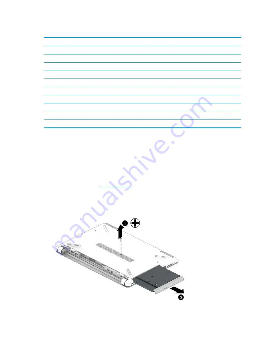
To remove the optical drive:

1.

Remove the Phillips PM2.5×6.0 screw (1) that secures the optical drive to the computer.

2.

Remove the optical drive (2) by sliding it out of the optical drive bay.

Component replacement procedures

33

Содержание 14-bw0 Series

Страница 1: ...HP 14 Laptop PC AMD Model numbers 14 bw0xx HP 14g Laptop PC Model numbers 14g bx0xx HP 14q Laptop PC Model numbers 14q by0xx Maintenance and Service Guide ...

Страница 2: ...rein is subject to change without notice The only warranties for HP products and services are set forth in the express warranty statements accompanying such products and services Nothing herein should be construed as constituting an additional warranty HP shall not be liable for technical or editorial errors or omissions contained herein First Edition April 2017 Document Part Number 927215 001 Pro...

Страница 3: ... another hard surface such as an adjoining optional printer or a soft surface such as pillows or rugs or clothing to block airflow Also do not allow the AC adapter to contact the skin or a soft surface such as pillows or rugs or clothing during operation The device and the AC adapter comply with the user accessible surface temperature limits defined by the International Standard for Safety of Info...

Страница 4: ...iv Safety warning notice ...

Страница 5: ...subcomponents 21 Mass storage devices 23 Cables 24 Miscellaneous parts 25 4 Removal and replacement procedures preliminary requirements 27 Tools required 27 Service considerations 27 Plastic parts 27 Cables and connectors 27 Drive handling 28 Grounding guidelines 28 Electrostatic discharge damage 28 Packaging and transporting guidelines 29 Workstation guidelines 29 5 Removal and replacement proced...

Страница 6: ...ector cable 71 Power button board 72 Top cover keyboard 73 7 Using Setup Utility BIOS 75 Starting Setup Utility BIOS 75 Updating Setup Utility BIOS 75 Determining the BIOS version 75 Downloading a BIOS update 76 8 Backing up restoring and recovering 77 Creating recovery media and backups 77 Creating HP Recovery media select products only 77 Using Windows tools 78 Restore and recovery 79 Recovering...

Страница 7: ...omputer specifications 85 35 6 cm 14 0 in display specifications 86 Hard drive specifications 87 M 2 solid state drive specifications 88 DVD RW SuperMulti DL Drive specifications 89 11 Power cord set requirements 91 Requirements for all countries 91 Requirements for specific countries and regions 92 12 Recycling 95 Index 97 vii ...

Страница 8: ...viii ...

Страница 9: ...icated video memory Support HD Decode DX12 and HDMI Supports PX7 Panel 35 6 cm 14 0 in high definition HD white light emitting diode WLED SVA BrightView 1366 768 display slim flat 3 0 mm eDP typical brightness 220 nits 35 6 cm 14 0 in high definition HD white light emitting diode WLED SVA anti glare 1366 768 display slim flat 3 0 mm eDP typical brightness 220 nits 35 6 cm 14 0 in full high definit...

Страница 10: ...28 in thicknesses Support for m 2 SATA SSD Single hard drive configurations 1 TB 5400 rpm 9 5 mm or 7 0 mm 500 GB 5400 rpm 7 0 mm M 2 SATA 3 configurations value 256 GB 128 GB M 2 SATA 3 configurations TLC 256 GB 128 GB eMMC configuration 128 GB 64 GB 32 GB Optical drive Fixed serial ATA 9 0 mm tray load DVD RW Double Layer writer Supports zero power optical drive Supports M disc Supports configur...

Страница 11: ...Intel Dual Band Wireless AC 7265 802 11AC 2x2 WiFi BT 4 2 Combo Adapter non vPro Intel Dual Band Wireless AC 3168 802 11AC 1x1 WiFi BT 4 2 Combo Adaptor non vPro External media card HP Multi Format Digital Media Reader Support SD SDHC SDXC Push pull insertion removal Internal Card One M 2 slot for SSD One M 2 slot for WLAN Ports VGA Dsub 15 pin supporting 1920 1200 60Hz HDMI version 1 4b supportin...

Страница 12: ...NB ML Compact Windows 10 Home Entry NB ML Compact Windows 10 Home Entry NB w OneDrive ML Compact For Emerging Market EM SL Windows 10 Home EM SL Windows 10 Home Value NB EM SL Windows 10 Home Value NB Select Geo EM SL For China Market CPPP Windows 10 Home High End China Language Edition CPPP Windows 10 Home China Language Edition For APJ SEAP Market EM SL SEAP Windows 10 Home EM SL SEAP Windows 10...

Страница 13: ...th connectors facing the computer 2 Insert the card into the memory card reader and then press in on the card until it is firmly seated To remove a card Pull the card out of the memory card reader 4 USB 2 0 port Connects a USB device such as a cell phone camera activity tracker or smartwatch and provides data transfer 5 Optical drive select products only Depending on your computer model reads an o...

Страница 14: ...harging 3 Vent Enables airflow to cool internal components NOTE The computer fan starts up automatically to cool internal components and prevent overheating It is normal for the internal fan to cycle on and off during routine operation 4 External monitor port select products only Connects an external VGA monitor or projector 5 RJ 45 network jack status lights Connects a network cable White The net...

Страница 15: ...io cable Also connects an optional headset microphone This jack does not support optional standalone microphones WARNING To reduce the risk of personal injury adjust the volume before putting on headphones earbuds or a headset For additional safety information refer to the Regulatory Safety and Environmental Notices To access this guide Select the Start button select HP Help and Support and then s...

Страница 16: ... sound The antennas are not visible from the outside of the computer and antenna location varies For optimal transmission keep the areas immediately around the antennas free from obstructions For wireless regulatory notices see the section of the Regulatory Safety and Environmental Notices that applies to your country or region To access this guide Select the Start button select HP Help and Suppor...

Страница 17: ...ad zone Reads your finger gestures to move the pointer or activate items on the screen 2 Left TouchPad button Functions like the left button on an external mouse 3 Right TouchPad button Functions like the right button on an external mouse Keyboard area 9 ...

Страница 18: ...nent Description 1 Caps lock light On Caps lock is on which switches the key input to all capital letters 2 Mute light Amber Computer sound is off Off Computer sound is on 10 Chapter 2 Getting to know your computer ...

Страница 19: ...ton briefly to exit Hibernation CAUTION Pressing and holding down the power button results in the loss of unsaved information If the computer has stopped responding and shutdown procedures are ineffective press and hold the power button down for at least 5 seconds to turn off the computer To learn more about your power settings see your power options Type power in the taskbar search box and then s...

Страница 20: ...fic functions when pressed in combination with another key 3 Windows key Opens the Start menu NOTE Pressing the Windows key again will close the Start menu 4 Action keys Execute frequently used system functions NOTE On select products the f5 action key turns the keyboard backlight feature off or on 12 Chapter 2 Getting to know your computer ...

Страница 21: ...display to the monitor display to a simultaneous display on both the computer and the monitor Turns the keyboard backlight off or on NOTE To conserve battery power turn off this feature Mutes or restores speaker sound Decreases speaker volume incrementally while you hold down the key Increases speaker volume incrementally while you hold down the key Plays the previous track of an audio CD or the p...

Страница 22: ...ase latch Releases the battery 4 Speakers 2 Produce sound 5 Vent Enables airflow to cool internal components NOTE The computer fan starts up automatically to cool internal components and prevent overheating It is normal for the internal fan to cycle on and off during routine operation 14 Chapter 2 Getting to know your computer ...

Страница 23: ...r the product number or the model number Locate these numbers before you contact support Your service label will resemble one of the examples shown below Refer to the illustration that most closely matches the service label on your computer Component 1 Serial number 2 Product number 3 Warranty period 4 Model number select products only Component 1 Model name select products only 2 Product number 3...

Страница 24: ...16 Chapter 2 Getting to know your computer ...

Страница 25: ...TE HP continually improves and changes product parts For complete and current information on supported parts for your computer go to http partsurfer hp com select your country or region and then follow the on screen instructions Computer major components 17 ...

Страница 26: ... speakers and cable 925376 001 5 Power connector cable 814142 013 6 USB board 925450 001 7 Power button board 925366 001 8 Hard drive bracket 925354 001 9 Hard drive 2 5 inch does not include bracket connector board or cable 1 TB 5400 rpm 778192 005 500 GB 5400 rpm 778186 005 10 Solid state drive M 2 256 GB 865902 018 128 GB 827560 049 10 eMMC module 128 GB 833958 007 64 GB 779066 023 32 GB 786461...

Страница 27: ...802 11 bgn 1x1 WiFi Adapter 927235 855 Intel Dual Band Wireless AC 3168 802 11 ac 1x1 WiFi BT 4 2 Combo Adapter 863934 855 15 RTC battery 746439 001 16 Memory modules 8 GB 862398 855 4 GB 862397 855 2 GB 864271 855 17 Fan 925352 001 Heat sink assembly includes replacement thermal materials 18 For use in models with discrete graphics memory 925452 001 19 For use in models with a fan and with UMA gr...

Страница 28: ...ss red 925657 001 Jack black 925322 001 For use in models without an optical drive Pike natural silver 925332 001 Silk gold 925333 001 Smoke gray 925330 001 Marine blue 925331 001 Jack black 925328 001 Snow white 925329 001 Empress red 925334 001 20 Chapter 3 Illustrated parts catalog ...

Страница 29: ...umber 1 Display bezel 925335 001 2 Raw display panel 35 6 cm 14 0 in FHD anti glare 821816 006 FHD BrightView 847660 009 HD anti glare 916357 005 HD BrightView 847664 009 3 Camera microphone module HD 919471 007 VGA 919472 007 Display assembly subcomponents 21 ...

Страница 30: ... 001 5 Hinge Kit left and right 925356 001 6 Display cable includes display panel cable and camera microphone cable 925342 001 7 Antenna includes wireless antenna cable and transceiver 925314 001 8 Display enclosure Pike natural silver 925319 001 Silk gold 925320 001 Smoke gray 925317 001 Marine blue 925318 001 Jack black 925315 001 Snow white 925316 001 Empress red 925321 001 22 Chapter 3 Illustr...

Страница 31: ...92 005 500 GB 5400 rpm 778186 005 2 Hard drive bracket 925354 001 3 Solid state drive M 2 256 GB 865902 018 128 GB 827560 049 4 Solid state drive bracket 925355 001 5 Optical drive DVD RW Double Layer SuperMulti 920417 001 6 Optical drive bezel Pike natural silver 925340 001 Silk gold 925341 001 Smoke gray 925338 001 Mass storage devices 23 ...

Страница 32: ...ite 925337 001 Empress red 925658 001 7 Optical drive bracket 925353 001 Cables Item Component Spare part number 1 USB board cable 925343 001 2 TouchPad button board cable 925344 001 3 TouchPad cable 925346 001 4 Power button board cable 925345 001 24 Chapter 3 Illustrated parts catalog ...

Страница 33: ...8 011 For use in Denmark 920688 007 For use in Europe 920688 005 For use in India 920688 016 For use in Italy 920688 002 For use in Japan 920688 017 For use in North America 920688 001 For use in the People s Republic of China 920688 014 For use in Thailand 920688 012 For use in the United Kingdom 920688 006 Power adapter For use in Japan 226768 001 Screw Kit 925375 001 Rubber Feet Kit Ash silver ...

Страница 34: ...26 Chapter 3 Illustrated parts catalog ...

Страница 35: ... and reassembly can damage plastic parts Use care when handling the plastic parts Apply pressure only at the points designated in the maintenance instructions Cables and connectors CAUTION When servicing the computer be sure that cables are placed in their proper locations during the reassembly process Improper cable placement can damage the computer Cables must be handled with extreme care to avo...

Страница 36: ... Electronic components are sensitive to electrostatic discharge ESD Circuitry design and structure determine the degree of sensitivity Networks built into many integrated circuits provide some protection but in many cases ESD contains enough power to alter device parameters or melt silicon junctions A discharge of static electricity from a finger or other conductor can destroy static sensitive dev...

Страница 37: ...ly Store reusable ESD sensitive parts from assemblies in protective packaging or non conductive foam Use transporters and conveyors made of antistatic belts and roller bushings Be sure that mechanized equipment used for moving materials is wired to ground and that proper materials are selected to avoid static charging When grounding is not possible use an ionizer to dissipate electric charges Work...

Страница 38: ...operator and ground To be effective the conductive must be worn in contact with the skin The following grounding equipment is recommended to prevent electrostatic damage Antistatic tape Antistatic smocks aprons and sleeve protectors Conductive bins and other assembly or soldering aids Nonconductive foam Conductive tabletop workstations with ground cords of one megohm resistance Static dissipative ...

Страница 39: ...gion and then follow the on screen instructions Component replacement procedures NOTE Please read and follow the procedures described here to access and replace Customer Self Repair parts successfully NOTE Details about your computer including model serial number product key and length of warranty are on the service tag at the bottom of your computer See Labels on page 15 for details This chapter ...

Страница 40: ...evices connected to the computer 3 Disconnect the power from the computer by first unplugging the power cord from the AC outlet and then unplugging the AC adapter from the computer To remove the battery 1 Position the computer upside down on a flat surface 2 Slide the battery lock latch 1 to unlock the battery and then slide the battery release latch 2 to release the battery NOTE The battery relea...

Страница 41: ...unsure whether the computer is off or in Hibernation turn the computer on and then shut it down through the operating system 2 Disconnect all external devices connected to the computer 3 Disconnect the power from the computer by first unplugging the power cord from the AC outlet and then unplugging the AC adapter from the computer 4 Remove the battery see Battery on page 32 To remove the optical d...

Страница 42: ...tate the side of the bezel 3 and the remove it 4 4 If it is necessary to replace the bracket on the rear of the optical drive remove the Phillips PM2 0 2 5 screw 1 that secures the bracket to the drive and then remove the bracket 2 Reverse this procedure to reassemble and install the optical drive 34 Chapter 5 Removal and replacement procedures for Customer Self Repair parts ...

Страница 43: ...Display subcomponents bezel panel camera NOTE Display assemblies are spared at the subcomponent level only This section illustrates how to remove the display bezel display panel and camera module without removing the display from the computer The Display assembly on page 62 section illustrates removing all display subcomponents To remove the display assembly subcomponents follow these steps 1 Shut...

Страница 44: ...ssembly with the top edge toward you b Pry up to disengage the camera microphone module from the adhesive that secures it to the display 1 c Disconnect the cable 2 from the module 4 To remove the display panel 36 Chapter 6 Removal and replacement procedures for Authorized Service Provider parts ...

Страница 45: ...b Rotate the display panel onto the keyboard 2 to gain access to the display cable connection on the back of the panel c On the back of the display panel release the adhesive strip that secures the display panel cable to the display panel and then disconnect the cable 1 Component replacement procedures 37 ...

Страница 46: ...ve the display panel from the computer 2 Reverse this procedure to reassemble and install the display assembly components 38 Chapter 6 Removal and replacement procedures for Authorized Service Provider parts ...

Страница 47: ...efore removing the bottom cover follow these steps 1 Shut down the computer If you are unsure whether the computer is off or in Hibernation turn the computer on and then shut it down through the operating system 2 Disconnect all external devices connected to the computer 3 Disconnect the power from the computer by first unplugging the power cord from the AC outlet and then unplugging the AC adapte...

Страница 48: ...cure the bottom cover to the computer 3 Use a plastic non marking tool 1 to pry the bottom cover from the computer 2 Reverse this procedure to install the bottom cover 40 Chapter 6 Removal and replacement procedures for Authorized Service Provider parts ...

Страница 49: ...the computer If you are unsure whether the computer is off or in Hibernation turn the computer on and then shut it down through the operating system 2 Disconnect all external devices connected to the computer 3 Disconnect the power from the computer by first unplugging the power cord from the AC outlet and then unplugging the AC adapter from the computer 4 Remove the battery see Battery on page 32...

Страница 50: ...ennas are not connected to the terminals on the WLAN module the protective sleeves must be installed on the antenna connectors as shown in the following illustration Reverse this procedure to install the WLAN module 42 Chapter 6 Removal and replacement procedures for Authorized Service Provider parts ...

Страница 51: ... from the computer by first unplugging the power cord from the AC outlet and then unplugging the AC adapter from the computer 4 Remove the battery see Battery on page 32 5 Remove the optical drive see Optical drive on page 33 if installed 6 Remove the bottom cover see Bottom cover on page 39 To remove a memory module 1 Spread the retaining tabs 1 on each side of the memory module slot to release t...

Страница 52: ...drive bracket Description Spare part number Hard drives 1 TB 5400 rpm 778192 005 500 GB 5400 rpm 778186 005 Hard drive bracket 925354 001 Before removing the hard drive follow these steps 1 Shut down the computer If you are unsure whether the computer is off or in Hibernation turn the computer on and then shut it down through the operating system 2 Disconnect all external devices connected to the ...

Страница 53: ...nnector 2 and the remove the hard drive assembly from the computer 3 3 To remove the hard drive bracket from the hard drive remove the four Phillips PM3 0 3 0 screws 1 that secure the bracket to the hard drive Component replacement procedures 45 ...

Страница 54: ... Remove the hard drive bracket from the hard drive 2 Reverse this procedure to reassemble and install the hard drive 46 Chapter 6 Removal and replacement procedures for Authorized Service Provider parts ...

Страница 55: ...55 001 Before removing the solid state drive eMMC adapter bracket follow these steps 1 Shut down the computer If you are unsure whether the computer is off or in Hibernation turn the computer on and then shut it down through the operating system 2 Disconnect all external devices connected to the computer 3 Disconnect the power from the computer by first unplugging the power cord from the AC outlet...

Страница 56: ...Disconnect the power from the computer by first unplugging the power cord from the AC outlet and then unplugging the AC adapter from the computer 4 Remove the battery see Battery on page 32 5 Remove the optical drive see Optical drive on page 33 if installed 6 Remove the bottom cover see Bottom cover on page 39 Remove the solid state drive 1 Remove the Phillips PM2 0 2 0 screw 1 that secures the d...

Страница 57: ...de of the computer Before removing the fan heat sink assembly follow these steps 1 Shut down the computer If you are unsure whether the computer is off or in Hibernation turn the computer on and then shut it down through the operating system 2 Disconnect all external devices connected to the computer 3 Disconnect the power from the computer by first unplugging the power cord from the AC outlet and...

Страница 58: ...3 Remove the fan from the computer 3 Reverse this procedure to install the fan 50 Chapter 6 Removal and replacement procedures for Authorized Service Provider parts ...

Страница 59: ... from the computer by first unplugging the power cord from the AC outlet and then unplugging the AC adapter from the computer 4 Remove the battery see Battery on page 32 5 Remove the optical drive see Optical drive on page 33 if installed 6 Remove the bottom cover see Bottom cover on page 39 To remove the TouchPad button board 1 Disconnect the cable from the TouchPad button board 1 2 Remove the tw...

Страница 60: ... through the ventilation grill located on the left side of the computer Before removing the heat sink assembly follow these steps 1 Shut down the computer If you are unsure whether the computer is off or in Hibernation turn the computer on and then shut it down through the operating system 2 Disconnect all external devices connected to the computer 3 Disconnect the power from the computer by first...

Страница 61: ...1 Discrete graphics Discrete graphics Thermal paste is used on the processor and associated heat sink area 1 2 as well as the graphics chip and associated heat sink area 3 4 4 Component replacement procedures 53 ...

Страница 62: ...Figure 6 2 UMA graphics UMA graphics Thermal paste is used on the heat sink 1 and the processor 2 5 54 Chapter 6 Removal and replacement procedures for Authorized Service Provider parts ...

Страница 63: ... UMA graphics fanless UMA graphics fanless Thermal paste is used on the heat sink 1 and the processor 2 Reverse this procedure to reassemble and install the heat sink assembly Component replacement procedures 55 ...

Страница 64: ...omputer by first unplugging the power cord from the AC outlet and then unplugging the AC adapter from the computer 4 Remove the battery see Battery on page 32 5 Remove the optical drive see Optical drive on page 33 if installed 6 Remove the bottom cover see Bottom cover on page 39 To remove the speakers 1 Disconnect the speaker cable from the system board 1 2 Remove the cable from its routing path...

Страница 65: ...4 Lift up and remove the speakers from the computer 4 Reverse this procedure to install the speakers Component replacement procedures 57 ...

Страница 66: ... AC outlet and then unplugging the AC adapter from the computer 4 Remove the battery see Battery on page 32 5 Remove the optical drive see Optical drive on page 33 if installed 6 Remove the bottom cover see Bottom cover on page 39 7 Remove the speakers see Speakers on page 56 To remove the USB board 1 Disconnect the cable from the connector on the USB board 1 2 Remove the Phillips PM2 5 5 0 screw ...

Страница 67: ...off or in Hibernation turn the computer on and then shut it down through the operating system 2 Disconnect all external devices connected to the computer 3 Disconnect the power from the computer by first unplugging the power cord from the AC outlet and then unplugging the AC adapter from the computer 4 Remove the battery see Battery on page 32 5 Remove the optical drive see Optical drive on page 3...

Страница 68: ...5 screws 1 that secure the system board to the computer 3 Rotate the side of the board upward 2 and then lift the system board out of the computer 3 Reverse this procedure to install the system board 60 Chapter 6 Removal and replacement procedures for Authorized Service Provider parts ...

Страница 69: ...uter by first unplugging the power cord from the AC outlet and then unplugging the AC adapter from the computer 4 Remove the battery see Battery on page 32 5 Remove the optical drive see Optical drive on page 33 if installed 6 Remove the bottom cover see Bottom cover on page 39 7 Remove the system board see System board on page 59 To remove the RTC battery 1 Position the system board upside down 2...

Страница 70: ...3 Disconnect the power from the computer by first unplugging the power cord from the AC outlet and then unplugging the AC adapter from the computer 4 Remove the battery see Battery on page 32 5 Remove the optical drive see Optical drive on page 33 if installed 6 Remove the bottom cover see Bottom cover on page 39 To remove the display assembly 1 Disconnect the display panel cable from the system b...

Страница 71: ... right edges 2 and the bottom edge 3 of the display bezel until the bezel disengages from the display enclosure NOTE When removing the bezel from the bottom of the display 3 be careful not to peel the Mylar from the bottom of the display panel b Remove the display bezel 4 NOTE The display will not be connected to the computer as shown in the following image Component replacement procedures 63 ...

Страница 72: ...era microphone module from the adhesive that secures it to the display 1 c Disconnect the cable 2 from the module 3 To remove the display panel a Remove the four Phillips PM2 0 3 0 screws 1 that secure the display panel to the top of the enclosure 64 Chapter 6 Removal and replacement procedures for Authorized Service Provider parts ...

Страница 73: ... the back of the panel NOTE The display will not be connected to the computer as shown in the following image c On the back of the display panel release the adhesive strip that secures the display panel cable to the display panel and then disconnect the cable 1 Component replacement procedures 65 ...

Страница 74: ...ay will not be connected to the computer as shown in the following image 4 To remove the display hinges a Pull either side of each hinge cap to disengage it from the enclosure 1 66 Chapter 6 Removal and replacement procedures for Authorized Service Provider parts ...

Страница 75: ...wo Phillips PM2 0 3 0 screws 1 and then lift the top display hinge 2 off the display d Remove the three broadhead Phillips PM2 5 3 0 screws 1 and the PM2 0 3 0 screw 2 that secure each hinge to the display enclosure Component replacement procedures 67 ...

Страница 76: ... the wireless antennas an cables release the cables from the clips built into the side of the display enclosure 1 and then remove the antennas and cables 2 3 68 Chapter 6 Removal and replacement procedures for Authorized Service Provider parts ...

Страница 77: ...To remove the display camera cable remove the cable from the clips built into the side of the display enclosure 1 and then remove the cable from the display enclosure 2 Component replacement procedures 69 ...

Страница 78: ...sure that the subcomponents including the camera microphone module the antenna receivers and all associated cables and hardware are transferred to the new enclosure Reverse this procedure to reassemble and install the display assembly 70 Chapter 6 Removal and replacement procedures for Authorized Service Provider parts ...

Страница 79: ... unplugging the power cord from the AC outlet and then unplugging the AC adapter from the computer 4 Remove the battery see Battery on page 32 5 Remove the optical drive see Optical drive on page 33 if installed 6 Remove the bottom cover see Bottom cover on page 39 7 Remove the display see Display assembly on page 62 To remove the power connector cable 1 Disconnect the power connector cable from t...

Страница 80: ... then unplugging the AC adapter from the computer 4 Remove the battery see Battery on page 32 5 Remove the optical drive see Optical drive on page 33 if installed 6 Remove the bottom cover see Bottom cover on page 39 7 Remove the display see Display assembly on page 62 To remove the power button board 1 Remove the Phillips PM2 0 3 0 screw 1 that secures the power button board to the computer 2 Rot...

Страница 81: ...pare part kits include TouchPad Description Spare part number Jet black 925307 xxx Snow white 925308 xxx Smoke gray 925309 xxx Marine blue 925310 xxx Pike silver 925311 xx1 Silk gold 925312 xx1 Empress red 925313 xx1 For use in country or region Spare part number For use in country or region Spare part number English French Canada DB1 Japan 291 Czech Republic and Slovakia FL1 The Netherlands B31 D...

Страница 82: ...74 Chapter 6 Removal and replacement procedures for Authorized Service Provider parts ...

Страница 83: ...e on the HP website Most BIOS updates on the HP website are packaged in compressed files called SoftPaqs Some download packages contain a file named Readme txt which contains information regarding installing and troubleshooting the file Determining the BIOS version To decide whether you need to update Setup Utility BIOS first determine the BIOS version on your computer To reveal the BIOS version i...

Страница 84: ...y the most recent BIOS update and compare it to the BIOS version currently installed on your computer If the update is more recent than your BIOS version make a note of the date name or other identifier You may need this information to locate the update later after it has been downloaded to your hard drive b Follow the on screen instructions to download your selection to the hard drive Make a note...

Страница 85: ...the HP Recovery partition on the computer The backup can be used to reinstall the original operating system in cases where the hard drive is corrupted or has been replaced For information on creating recovery media see Creating HP Recovery media select products only on page 77 For information on the recovery options that are available using the recovery media see Using Windows tools on page 78 Use...

Страница 86: ...arately to create recovery discs If you use an external optical drive it must be connected directly to a USB port on the computer the drive cannot be connected to a USB port on an external device such as a USB hub If you cannot create DVD media yourself you can obtain recovery discs for your computer from HP See the Worldwide Telephone Numbers booklet included with the computer You can also find c...

Страница 87: ...o remove the Recovery partition to reclaim hard drive space HP Recovery Manager offers the Remove Recovery Partition option For more information see Removing the HP Recovery partition select products only on page 82 Recovering using HP Recovery Manager HP Recovery Manager software allows you to recover the computer to its original factory state by using the HP Recovery media that you either create...

Страница 88: ...rking To start HP Recovery Manager from the HP Recovery partition IMPORTANT For a tablet with a detachable keyboard connect the tablet to the keyboard base before beginning these steps select products only 1 Type recovery in the taskbar search box select Recovery Manager and then select HP Recovery Environment or For computers or tablets with keyboards attached press f11 while the computer boots o...

Страница 89: ...ard base before beginning these steps 1 Insert the HP Recovery media 2 Access the system Startup menu For computers or tablets with keyboards attached Turn on or restart the computer or tablet quickly press esc and then press f9 for boot options For tablets without keyboards Turn on or restart the tablet and then quickly hold down the volume up button then select f9 or Turn on or restart the table...

Страница 90: ...overy partition So before you remove the Recovery partition create HP Recovery media see Creating HP Recovery media select products only on page 77 NOTE The Remove Recovery Partition option is only available on products that support this function Follow these steps to remove the HP Recovery partition 1 Type recovery in the taskbar search box and then select HP Recovery Manager 2 Select Remove Reco...

Страница 91: ...lowing order a Connected USB drive NOTE To download the HP PC Hardware Diagnostics UEFI tool to a USB drive see Downloading HP PC Hardware Diagnostics UEFI to a USB device on page 83 b Hard drive c BIOS 3 When the diagnostic tool opens select the type of diagnostic test you want to run and then follow the on screen instructions NOTE If you need to stop a diagnostic test press esc Downloading HP PC...

Страница 92: ...ides a BIOS crisis recovery tool through the HP PC Hardware Diagnostics 3 in 1 USB key This tool can be used by HP authorized service providers to recover systems that have failed due to a corrupted BIOS For more information about using the 3 in 1 USB key for BIOS crisis recovery go to http www hp com go techcenter pcdiags Additional information is included in the web based training offered by HP ...

Страница 93: ... V dc 2 31 A 45 W Temperature Operating 5 C to 35 C 41 F to 95 F Nonoperating 20 C to 60 C 4 F to 140 F Relative humidity noncondensing Operating 10 to 90 Nonoperating 5 to 95 Maximum altitude unpressurized Operating 15 m to 3 048 m 50 ft to 10 000 ft Nonoperating 15 m to 12 192 m 50 ft to 40 000 ft NOTE Applicable product safety standards specify thermal limits for plastic surfaces The device ope...

Страница 94: ... diagonal size 35 6 cm 14 0 in Resolution 1366x768 HD 1920x1080 FHD Surface treatment BrightView Anti glare Brightness 220 nits Viewing angle SVA HD displays UWVA FHD displays Backlight WLED Graphics adapter eDP Thickness 3 0 mm 86 Chapter 10 Specifications ...

Страница 95: ... ATA security Seek times typical read including setting Single track 2 0 ms 3 ms Average read write 12 ms 13 ms Maximum 22 ms 24 ms Logical blocks 1 953 525 168 1 048 576 000 Disk rotational speed 5400 rpm 5400 rpm Operating temperature 1 GB 1 billion bytes when referring to hard drive storage capacity Actual accessible capacity is less NOTE Certain restrictions and exclusions apply Contact techni...

Страница 96: ...B s Up to 34K IOPs Up to 280 MB s Up to 67K IOPs Ready time Maximum to not busy 1 0 s 1 0 s Access times Logical 0 1 ms 0 1 Total logical sectors 250 069 680 500 118 192 Operating temperature Operating Non operating 0 to 70 C 32 F to 158 F 40 to 95 C 40 F to 203 F 0 to 70 C 32 F to 158 F 55 to 90 C 67 F to 194 F 1 GB 1 billion bytes when referring to hard drive storage capacity Actual accessible c...

Страница 97: ...iameter Standard disc 12 cm 4 72 in Mini disc 8 cm 3 15 in Disc thickness 1 2 mm 0 047 in Track pitch 0 74 µm Access time CD DVD Random 175 ms 230 ms Full stroke 285 ms 335 ms Audio output level Line out 0 7 Vrms Cache buffer 2 MB Data transfer rate 24X CD ROM 3 600 KB sec 8X DVD ROM 10 800 KB sec 24X CD R 3 600 KB sec 16X CD RW 2 400 KB sec 8X DVD R 10 800 KB sec 4X DVD RW 5 400 KB sec 8X DVD R 1...

Страница 98: ...90 Chapter 10 Specifications ...

Страница 99: ...ng requirements are applicable to all countries and regions The length of the power cord set must be at least 1 5 m 5 0 ft and no more than 2 0 m 6 5 ft All power cord sets must be approved by an acceptable accredited agency responsible for evaluation in the country or region where the power cord set will be used The power cord sets must have a minimum current capacity of 10 A and a nominal voltag...

Страница 100: ...orea KTL 5 Sweden SEMKO 1 Switzerland SEV 1 Taiwan BSMI 6 Thailand TISI 1 The United Kingdom ASTA 1 The United States UL 2 1 The flexible cord must be Type HO5VV F 3 conductor 0 75mm2 conductor size Power cord set fittings appliance coupler and wall plug must bear the certification mark of the agency responsible for evaluation in the country or region where it will be used 2 The flexible cord must...

Страница 101: ...wall plug must bear the CCC certification mark 5 The flexible cord must be Type H05VV F 3X0 75mm2 conductor size KTL logo and individual approval number must be on each element Corset approval number and logo must be printed on a flag label 6 The flexible cord must be Type HVCTF 3X1 25mm2 conductor size Power cord set fittings appliance coupler cable and wall plug must bear the BSMI certification ...

Страница 102: ...94 Chapter 11 Power cord set requirements ...

Страница 103: ...he battery in general household waste Follow the local laws and regulations in your area for battery disposal HP encourages customers to recycle used electronic hardware HP original print cartridges and rechargeable batteries For more information about recycling programs see the HP Web site at http www hp com recycle 95 ...

Страница 104: ...96 Chapter 12 Recycling ...

Страница 105: ...mputer specifications 85 connector power 6 connectors service considerations 27 D display assembly illustrated 18 removing 62 display assembly subcomponents illustrated 21 removing 62 display bezel illustrated 21 removing 35 63 display cable illustrated 22 removing 66 display enclosure illustrated 22 removing 70 display panel illustrated 21 product description 1 removing 36 64 66 display specifica...

Страница 106: ...ted 19 product description 1 removing 43 microphone 2 minimized image recovery 80 minimized image creating 79 model name 1 mute light identifying 10 N network jack identifying 6 O operating system 4 optical drive illustrated 19 23 precautions 28 product description 2 removing 33 specifications 89 optical drive bracket illustrated 23 24 33 optical drive eject button identifying 5 optical drive rear...

Страница 107: ...3 solid state drive eMMC bracket illustrated 18 speakers illustrated 18 removing 56 speakers identifying 14 specifications computer 85 display 86 DVD RW SuperMulti DL Drive 89 hard drive 87 M 2 solid state drive 88 optical drive 89 supported discs recovery 78 system board removing 59 spare part number 18 59 system recovery 79 system restore point creating 78 system restore point creating 77 T tool...

Страница 108: ...100 Index ...

Отзывы: