background image

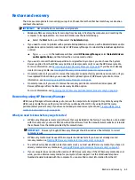
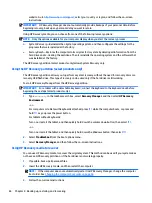
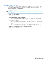
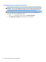
Removing the HP Recovery partition (select products only)

HP Recovery Manager software allows you to remove the HP Recovery partition to free up hard drive space.

IMPORTANT:

After you remove the HP Recovery partition, you will not be able to perform System Recovery 

or create HP recovery media from the HP Recovery partition. So before you remove the Recovery partition, 
create HP Recovery media; see 

Creating HP Recovery media (select products only) on page 61

.

NOTE:

The Remove Recovery Partition option is only available on products that support this function.

Follow these steps to remove the HP Recovery partition:

1.

Type 

recovery

 in the taskbar search box, and then select HP Recovery Manager.

2.

Select Remove Recovery Partition, and then follow the on-screen instructions.

66

Chapter 9   Backing up, restoring, and recovering

Содержание 13-d000

Страница 1: ...HP ENVY Notebook PC model numbers 13 d000 through 13 d099 and 13 d100 through 13 d199 Maintenance and Service Guide ...

Страница 2: ...our computer Not all features are available in all editions of Windows 10 This computer may require upgraded and or separately purchased hardware drivers and or software to take full advantage of Windows 10 functionality See http www microsoft com for details The information contained herein is subject to change without notice The only warranties for HP products and services are set forth in the e...

Страница 3: ...hat should only be accessed by an authorized service provider See Chapter 5 Removal and replacement procedures for Customer Self Repair parts for details Accessing parts described in Chapter 6 Removal and replacement procedures for Authorized Service Provider only parts can damage the computer or void your warranty iii ...

Страница 4: ...iv Important Notice about Customer Self Repair Parts ...

Страница 5: ...ow another hard surface such as an adjoining optional printer or a soft surface such as pillows or rugs or clothing to block airflow Also do not allow the AC adapter to contact the skin or a soft surface such as pillows or rugs or clothing during operation The device and the AC adapter comply with the user accessible surface temperature limits defined by the International Standard for Safety of In...

Страница 6: ...vi Safety warning notice ...

Страница 7: ... components 14 Display assembly subcomponents 18 Miscellaneous parts 20 4 Removal and replacement procedures preliminary requirements 21 Tools required 21 Service considerations 21 Plastic parts 21 Cables and connectors 22 Drive handling 22 Grounding guidelines 23 Electrostatic discharge damage 23 Packaging and transporting guidelines 24 Workstation guidelines 24 Equipment guidelines 25 5 Removal ...

Страница 8: ... Diagnostics UEFI 58 Downloading HP PC Hardware Diagnostics UEFI to a USB device 58 8 Specifications 60 Computer specifications 60 9 Backing up restoring and recovering 61 Creating recovery media and backups 61 Creating HP Recovery media select products only 61 Using Windows tools 62 Restore and recovery 63 Recovering using HP Recovery Manager 63 What you need to know before you get started 63 Usi...

Страница 9: ...Requirements for specific countries and regions 67 11 Recycling 69 Index 70 ix ...

Страница 10: ...x ...

Страница 11: ... eDP typical brightness 300 nits Memory Support for LPDDR3 1600 dual channel onboard memory Support for 8192 MB maximum system RAM in the following configurations 8192 MB 16 GB 256 MB 16 4 4 pieces 4096 MB 8 GB 128 MB 32 2 4 pieces Solid state drive Support for M2 Serial ATA storage Support for the following solid state drive configurations 512 MB M2 SATA 3 supporting triple level cell TLC 256 MB ...

Страница 12: ...nts ClickPad with image sensor MultiTouch gestures enabled Support for modern TrackPad gestures Taps enables as default Power requirements Support for 65 W HP Smart AC adapter non PFC EM 3 wire 4 5 mm and 45 W HP Smart AC adapter non PFC RC 3 wire 4 5 mm 1 0 meter 3 2 feet power cord Support for 6 cell 44 Wh 1 98 Ah Li ion battery Security Support for security cable lock Support for Trusted Platfo...

Страница 13: ...app A list displays all the devices installed on your computer For information about system hardware components and the system BIOS version number press fn esc select products only Locating software To find out what software is installed on your computer Select the Start button and then select All apps or Right click the Start button and then select Programs and Features Locating hardware 3 ...

Страница 14: ...itch Turns off the display and initiates Sleep if the display is closed while the power is on NOTE The internal display switch is not visible from the outside of the computer The antennas are not visible on the outside of the computer For optimal transmission keep the areas immediately around the antennas free from obstructions To see wireless regulatory notices see the section of the Regulatory S...

Страница 15: ...hen the computer is in Hibernation press the button briefly to exit Hibernation CAUTION Pressing and holding down the power button results in the loss of unsaved information If the computer has stopped responding and shutdown procedures are ineffective press and hold the power button down for at least 5 seconds to turn off the computer To learn more about your power settings see your power options...

Страница 16: ...s system information when pressed in combination with the fn key 2 fn key Executes frequently used system functions when pressed in combination with the esc key action keys or the spacebar 3 Windows key Opens the Start menu NOTE Pressing the Windows key again will close the Start menu 4 Action keys Execute frequently used system functions NOTE On select products the f5 action key turns the backlig...

Страница 17: ...e Sleep state a power saving state The computer shuts off power to the display and other unneeded components Off The computer is off or in Hibernation Hibernation is a power saving state that uses the least amount of power 2 Mute light Amber Computer sound is off Off Computer sound is on 3 Caps lock light On Caps lock is on which switches the key input to all capital letters Lights 7 ...

Страница 18: ...onent Description 1 TouchPad zone Reads finger gestures to move the pointer or activate items on the screen 2 Left TouchPad button Functions like the left button on an external mouse 3 Right TouchPad button Functions like the right button on an external mouse 8 Chapter 2 External component identification ...

Страница 19: ...use external drive printer scanner or USB hub Standard USB ports will not charge all USB devices or will charge using a low current Some USB devices require power and require you to use a power port NOTE USB charging ports can also charge select models of cell phones and MP3 players even when the computer is off 4 Audio out headphone audio in microphone combo jack Connects optional powered stereo ...

Страница 20: ...ernal drive printer scanner or USB hub 3 HDMI port Connects an optional video or audio device such as a high definition television any compatible digital or audio component or a high speed High Definition Multimedia Interface HDMI device 4 AC adapter light White The AC adapter is connected and the battery is fully charged Blinking white The AC adapter is disconnected and the battery has reached a ...

Страница 21: ... in this section Component Description Vents 2 Enable airflow to cool internal components NOTE The computer fan starts up automatically to cool internal components and prevent overheating It is normal for the internal fan to cycle on and off during routine operation Bottom 11 ...

Страница 22: ...t name This is the product name affixed to the front of the computer 2 Serial number s n This is an alphanumeric identifier that is unique to each product 3 Part number Product number p n This number provides specific information about the product s hardware components The part number helps a service technician to determine what components and parts are needed 12 Chapter 3 Illustrated parts catalo...

Страница 23: ... 4 Warranty period This number describes the duration of the warranty period for the computer 5 Model description This is the alphanumeric identifier used to locate documents drivers and support for the computer Service tag 13 ...

Страница 24: ...Computer major components 14 Chapter 3 Illustrated parts catalog ...

Страница 25: ... For use in the Netherlands 829305 B31 For use in Portugal 829305 131 For use in Russia 829305 251 For use in Saudi Arabia 829305 171 For use in South Korea 829305 AD1 For use in Spain 829305 071 For use in Switzerland 829305 BG1 For use in Taiwan 829305 AB1 For use in Thailand 829305 281 For use in Turkey 829305 141 For use in the United Kingdom and Singapore 829305 031 For use in the United Stat...

Страница 26: ...Hz processor 1600 MHz FSB 4 0 MB L3 cache dual core 15 W dynamic PL1 to 8 5 W 8 0 GB of system memory and the Windows 10 Professional operating system 829286 601 Equipped with an Intel Core i7 6500U 2 50 GHz SC turbo up to 3 10 GHz processor 1600 MHz FSB 4 0 MB L3 cache dual core 15 W dynamic PL1 to 8 5 W 8 0 GB of system memory and a non Windows operating system 829286 001 Equipped with an Intel ...

Страница 27: ... 829314 001 19 3 cell 45 Wh 3 83 Ah Li ion battery includes cable 816238 850 20 RTC battery includes cable and double sided adhesive 829306 001 21 Speaker Kit includes left and right speakers and cables 829309 001 22 Bottom cover includes two rear rubber feet one front rubber foot speaker grilles shielding and retention brackets 829289 001 and 848658 001 Rubber Kit not illustrated includes front r...

Страница 28: ...199 848174 001 For use only on computers with model numbers 13 d000 through 13 d099 833481 001 3 Webcam microphone module includes two microphone rubber isolators and double sided adhesive For use only on computers with model numbers 13 d100 through 13 d199 854982 001 For use only on computers with model numbers 13 d000 through 13 d099 833512 001 4 Display panel 18 Chapter 3 Illustrated parts cata...

Страница 29: ...through 13 d099 829303 001 6 Display hinge strip 829304 001 7 WLAN antenna includes left and right WLAN cables and transceivers For use only on computers with model numbers 13 d100 through 13 d199 848170 001 For use only on computers with model numbers 13 d000 through 13 d099 829287 001 8 Display panel cable includes webcam microphone module cable For use only on computer models equipped with a QH...

Страница 30: ...ack 1 00 m For use in Australia 755530 011 For use in Denmark 755530 081 For use in Europe 755530 021 For use in India 755530 D61 For use in Italy 755530 061 For use in Japan 755530 291 For use in North America 755530 001 For use in the People s Republic of China 755530 AA1 For use in South Korea 755530 AD1 For use in Switzerland 755530 111 For use in Taiwan 755530 AB1 For use in Thailand 755530 2...

Страница 31: ...ns The following sections include some of the considerations that you must keep in mind during disassembly and assembly procedures NOTE As you remove each subassembly from the computer place the subassembly and all accompanying screws away from the work area to prevent damage Plastic parts CAUTION Using excessive force during disassembly and reassembly can damage plastic parts Use care when handli...

Страница 32: ...ut down the computer If you are unsure whether the computer is off or in Hibernation turn the computer on and then shut it down through the operating system Before handling a drive be sure that you are discharged of static electricity While handling a drive avoid touching the connector Before removing a diskette drive or optical drive be sure that a diskette or disc is not in the drive and be sure...

Страница 33: ...ve these precautions Keep components in their electrostatic safe containers until you are ready to install them Before touching an electronic component discharge static electricity by using the guidelines described in this section Avoid touching pins leads and circuitry Handle electronic components as little as possible If you remove a component place it in an electrostatic safe container The foll...

Страница 34: ...er materials are selected to avoid static charging When grounding is not possible use an ionizer to dissipate electric charges Workstation guidelines Follow these grounding workstation guidelines Cover the workstation with approved static shielding material Use a wrist strap connected to a properly grounded work surface and use properly grounded tools and equipment Use conductive field service too...

Страница 35: ...m resistance between the operator and ground To be effective the conductive must be worn in contact with the skin The following grounding equipment is recommended to prevent electrostatic damage Antistatic tape Antistatic smocks aprons and sleeve protectors Conductive bins and other assembly or soldering aids Nonconductive foam Conductive tabletop workstations with ground cords of one megohm resis...

Страница 36: ...over spare part kit includes two rear rubber feet one front rubber foot speaker grilles shielding and retention brackets Description Spare part number Bottom cover includes two rear rubber feet one front rubber foot speaker grilles shielding and retention brackets 829289 001 and 848658 001 Before disassembling the computer follow these steps 1 Turn off the computer If you are unsure whether the co...

Страница 37: ...ed tool between the front edge of the bottom cover and keyboard top cover 5 Separate the front edge 2 of the bottom cover from keyboard top cover 6 Remove the bottom cover 3 NOTE If it is necessary to replace the bottom cover be sure to remove the bottom cover retention brackets from the defective bottom cover and install them on the replacement bottom cover To remove the bottom cover retention br...

Страница 38: ...off or in Hibernation turn the computer on and then shut it down through the operating system 2 Disconnect the power from the computer by unplugging the power cord from the computer 3 Disconnect all external devices from the computer 4 Remove the bottom cover see Bottom cover on page 26 Remove the battery 1 Disconnect the battery cable 1 from the system board 2 Remove the four Phillips PM2 5 4 4 s...

Страница 39: ...g the solid state drive follow these steps 1 Turn off the computer If you are unsure whether the computer is off or in Hibernation turn the computer on and then shut it down through the operating system 2 Disconnect the power from the computer by unplugging the power cord from the computer 3 Disconnect all external devices from the computer 4 Remove the bottom cover see Bottom cover on page 26 5 D...

Страница 40: ...id state drive WLAN module bracket is included in the Solid state Drive Hardware Kit spare part number 829300 001 3 Lift the edge of the solid state drive 1 opposite of the slot until it rests at an angle 4 Remove the solid state drive 2 by pulling the drive away from the slot at an angle Reverse this procedure to install the solid state drive 30 Chapter 5 Removal and replacement procedures ...

Страница 41: ...urn off the computer If you are unsure whether the computer is off or in Hibernation turn the computer on and then shut it down through the operating system 2 Disconnect the power from the computer by unplugging the power cord from the computer 3 Disconnect all external devices from the computer 4 Remove the bottom cover see Bottom cover on page 26 5 Disconnect the battery cable from the system bo...

Страница 42: ... antenna cable labeled 2 AUX connects to the WLAN module Aux terminal 6 Remove the WLAN module 4 NOTE If the WLAN antennas are not connected to the WLAN module the protective sleeve should be installed on the antenna connectors as shown in the following illustration Reverse this procedure to install the WLAN module 32 Chapter 5 Removal and replacement procedures ...

Страница 43: ...ect the power from the computer by unplugging the power cord from the computer 3 Disconnect all external devices from the computer 4 Remove the bottom cover see Bottom cover on page 26 5 Remove the battery see Battery on page 28 Remove the speakers 1 Disconnect the speaker cable 1 from the system board 2 Release the speaker cables from the retention clips 2 and channels built into the keyboard top...

Страница 44: ...he computer by unplugging the power cord from the computer 3 Disconnect all external devices from the computer 4 Remove the bottom cover see Bottom cover on page 26 5 Remove the battery see Battery on page 28 Remove the fingerprint reader board 1 Release the zero insertion force ZIF connector 1 to which the fingerprint reader board cable is attached and then disconnect the fingerprint reader board...

Страница 45: ... whether the computer is off or in Hibernation turn the computer on and then shut it down through the operating system 2 Disconnect the power from the computer by unplugging the power cord from the computer 3 Disconnect all external devices from the computer 4 Remove the bottom cover see Bottom cover on page 26 5 Remove the battery see Battery on page 28 Remove the TouchPad board 1 Release the ZIF...

Страница 46: ...omputer 3 Disconnect all external devices from the computer 4 Remove the bottom cover see Bottom cover on page 26 5 Disconnect the battery cable from the system board see Battery on page 28 Remove the power connector cable 1 Disconnect the power connector cable 1 from the system board 2 Release the power connector cable 2 from the routing channel built into the system board 3 Remove the two Philli...

Страница 47: ...omputer by unplugging the power cord from the computer 3 Disconnect all external devices from the computer 4 Remove the bottom cover see Bottom cover on page 26 5 Disconnect the battery cable from the system board see Battery on page 28 Remove the fans 1 Disconnect the fan cables 1 from the system board 2 Release the display panel cable from the routing clips built into the left fan 2 3 Release th...

Страница 48: ...rn the computer on and then shut it down through the operating system 2 Disconnect the power from the computer by unplugging the power cord from the computer 3 Disconnect all external devices from the computer 4 Remove the bottom cover see Bottom cover on page 26 5 Disconnect the battery cable from the system board see Battery on page 28 Remove the security cable slot bracket 1 Remove the Phillips...

Страница 49: ...200U 2 30 GHz SC turbo up to 2 80 GHz processor 1600 MHz FSB 3 0 MB L3 cache dual core 15 W dynamic PL1 to 8 5 W 8 0 GB of system memory and a non Windows operating system 829285 001 Equipped with an Intel Core i5 6200U 2 30 GHz SC turbo up to 2 80 GHz processor 1600 MHz FSB 3 0 MB L3 cache dual core 15 W dynamic PL1 to 8 5 W 4 0 GB of system memory and the Windows 10 Professional operating system...

Страница 50: ...d Power connector bracket see Power connector cable on page 36 e Fans see Fan on page 37 NOTE When replacing the system board be sure that the heat sink is removed from the defective system board and installed on the replacement system board See see Heat sink on page 43 for heat sink removal and replacement instructions Remove the system board 1 Release the adhesive support strip 1 that secures th...

Страница 51: ...rd cable from the system board 7 Release the ZIF connector 3 to which the keyboard cable is attached and then disconnect the keyboard cable from the system board 8 Disconnect the speaker cable 4 from the system board 9 Remove the Phillips PM2 5 3 4 screw 1 that secures the system board to the keyboard top cover 10 Remove the Phillips PM2 5 4 4 screw 2 that secures the system board and the left I O...

Страница 52: ...angle 13 Slide the system board 2 up and to the left at an angle until the connectors on the right side of the system board are clear of the openings on the right side of the keyboard top cover 14 Swing the rear edge of the system board 3 up and forward until the system board rests upside down on the keyboard top cover 42 Chapter 5 Removal and replacement procedures ...

Страница 53: ...off or in Hibernation turn the computer on and then shut it down through the operating system 2 Disconnect the power from the computer by unplugging the power cord from the computer 3 Disconnect all external devices from the computer 4 Remove the bottom cover see Bottom cover on page 26 and then remove the following components a Battery see Battery on page 28 b Solid state drive see Solid state dr...

Страница 54: ...ial located between the heat sink and the system board components it may be necessary to move the heat sink from side to side to detach it NOTE The thermal material must be thoroughly cleaned from the surfaces of the heat sink and the system board each time the heat sink is removed Replacement thermal material is included with the heat sink and system board spare part kits Thermal paste is used on...

Страница 55: ...power cord from the computer 3 Disconnect all external devices from the computer 4 Remove the bottom cover see Bottom cover on page 26 and then remove the following components a Battery see Battery on page 28 b Solid state drive see Solid state drive on page 29 c WLAN module see WLAN module on page 31 d Power connector bracket see Power connector cable on page 36 e Fans see Fan on page 37 f System...

Страница 56: ...ower from the computer by unplugging the power cord from the computer 3 Disconnect all external devices from the computer 4 Remove the bottom cover see Bottom cover on page 26 and then remove the following components a Battery see Battery on page 28 b Solid state drive see Solid state drive on page 29 c WLAN module see WLAN module on page 31 d Power connector bracket see Power connector cable on p...

Страница 57: ...display assembly 5 If it is necessary to replace the display bezel or any of the display assembly subcomponents a Remove the two display bezel screw covers 1 The display bezel screw covers are available using spare part numbers 848174 001 for use only on computers with model numbers 13 d100 through 13 d199 and 833481 001 for use only on computers with model numbers 13 d000 through 13 d099 Componen...

Страница 58: ...f the display bezel If this caution is not followed the display bezel can be damaged c Flex the inside edges of the right edge 2 the top edge 3 the left edge 4 and the bottom edge 5 of the display bezel until the bezel disengages from the display back cover d Remove the display bezel 6 The display bezel is available using spare part numbers 833480 001 and 857386 001 6 If it is necessary to replace...

Страница 59: ...can result in damage to the display panel c Lift the top edge of the display panel 1 and swing it up and forward until it rests upside down in front of the display back cover d Release the adhesive strip 2 that secures the display panel cable connector to the display panel e Disconnect the display panel cable 3 from the display panel f Remove the display panel The display panel is available using ...

Страница 60: ...e display panel c Release the two pieces of grounding tape 1 the secure the webcam microphone module cable to the display back cover d Disconnect the webcam microphone module cable 2 from the webcam microphone module e Detach the webcam microphone module 3 from the display back cover The webcam microphone module is attached to the display back cover with double sided adhesive NOTE When releasing t...

Страница 61: ...he display hinges e Remove the display hinges 2 The display hinges are available using spare part numbers 848176 001 for use only on computers with model numbers 13 d100 through 13 d199 and 829303 001 for use only on computers with model numbers 13 d000 through 13 d099 f If it is necessary to replace the hinge strip remove the two Phillips PM2 0 2 4 screws 1 that secure the hinge strip to the disp...

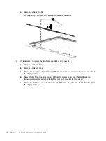
Страница 62: ...o pieces of grounding tape 1 the secure the webcam microphone module cable to the display back cover d Detach the WLAN antenna transceivers 2 from the display back cover The WLAN antenna transceivers are attached to the display back cover with double sided adhesive e Release the WLAN antenna cables from the clips 3 and routing channel built into the left edge of the display back cover 52 Chapter 5...

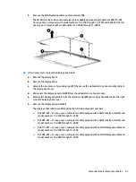
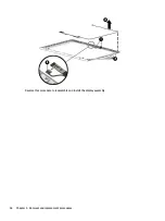
Страница 63: ...rophone module e Release the display panel cable from the retention clips 3 and routing channel built into the right side of the display back cover f Remove the display panel cable 4 The display panel cable is available using the following spare part numbers 854981 001 For use only on computer models equipped with a QHD display assembly and model numbers 13 d100 through 13 d199 833483 001 For use ...

Страница 64: ...Reverse this procedure to reassemble and install the display assembly 54 Chapter 5 Removal and replacement procedures ...

Страница 65: ...rd attached to your notebook The on screen keyboard which displays in tablet mode cannot access Setup Utility Computers or tablets with keyboards Turn on or restart the computer quickly press esc and then press f10 Tablets without keyboards 1 Turn on or restart the tablet and then quickly hold down the volume down button or Turn on or restart the tablet and then quickly hold down the Windows butto...

Страница 66: ...dministrator before installing any software updates especially system BIOS updates 1 Type support in the taskbar search box and then select the HP Support Assistant app or Click the question mark icon in the taskbar 2 Click Updates and then click Check for updates and messages 3 Follow the on screen instructions 4 At the download area follow these steps a Identify the most recent BIOS update and c...

Страница 67: ...le keyboard when you attach the tablet to the keyboard and restart the computer Setup Utility BIOS checks to see if the Embedded Controller firmware on the keyboard needs to be synchronized If so synchronization begins If the synchronization is interrupted a notification screen displays for 10 seconds before the tablet restarts and attempts to synchronize again NOTE The Embedded Controller firmwar...

Страница 68: ...urn on or restart the tablet and then quickly hold down the Windows button 2 Press or tap f2 The BIOS searches three places for the diagnostic tools in the following order a Connected USB drive NOTE To download the HP PC Hardware Diagnostics UEFI tool to a USB drive see Downloading HP PC Hardware Diagnostics UEFI to a USB device on page 58 b Hard drive c BIOS 3 When the diagnostic tool opens selec...

Страница 69: ...ownloads 3 In the text box enter the product name and then click Go or Click Find Now to let HP automatically detect your product 4 Select your computer and then select your operating system 5 In the Diagnostic section follow the on screen instructions to select and download the UEFI version you want Downloading HP PC Hardware Diagnostics UEFI to a USB device 59 ...

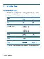
Страница 70: ...eight 1 3 cm 0 51 in Weight 1 4 kg 3 01 lbs Input power Operating voltage and current 19 5 V dc 2 31 A 45 W 19 5 V dc 3 33 A 65 W 19 5 V dc 4 62 A 90 W 19 5 V dc 6 15 A 120 W 19 5 V dc 7 69 A 150 W Temperature Operating 5 C to 35 C 41 F to 95 F Nonoperating 20 C to 60 C 4 F to 140 F Relative humidity noncondensing Operating 10 to 90 Nonoperating 5 to 95 Maximum altitude unpressurized Operating 15 ...

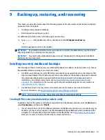
Страница 71: ... the HP Recovery partition on the computer The backup can be used to reinstall the original operating system in cases where the hard drive is corrupted or has been replaced For information on creating recovery media see Creating HP Recovery media select products only on page 61 For information on the recovery options that are available using the recovery media see Using Windows tools on page 62 Us...

Страница 72: ...rately to create recovery discs If you use an external optical drive it must be connected directly to a USB port on the computer the drive cannot be connected to a USB port on an external device such as a USB hub If you cannot create DVD media yourself you can obtain recovery discs for your computer from HP See the Worldwide Telephone Numbers booklet included with the computer You can also find co...

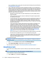
Страница 73: ...o remove the recovery partition to reclaim hard drive space HP Recovery Manager offers the Remove Recovery Partition option For more information see Removing the HP Recovery partition select products only on page 66 Recovering using HP Recovery Manager HP Recovery Manager software allows you to recover the computer to its original factory state by using the HP Recovery media that you either create...

Страница 74: ...rking To start HP Recovery Manager from the HP Recovery partition IMPORTANT For a tablet with a detachable keyboard connect the keyboard to the keyboard dock before beginning these steps select products only 1 Type recovery in the taskbar search box select Recovery Manager and then select HP Recovery Environment or For computers or tablets with keyboards attached press f11 while the computer boots...

Страница 75: ...to the keyboard dock before beginning these steps 1 Insert the HP Recovery media 2 Access BIOS For computers or tablets with keyboards attached Turn on or restart the computer or tablet quickly press esc and then press f9 for boot options For tablets without keyboards Turn on or restart the tablet and then quickly hold down the volume down button then select f9 or Turn on or restart the tablet and...

Страница 76: ...overy partition So before you remove the Recovery partition create HP Recovery media see Creating HP Recovery media select products only on page 61 NOTE The Remove Recovery Partition option is only available on products that support this function Follow these steps to remove the HP Recovery partition 1 Type recovery in the taskbar search box and then select HP Recovery Manager 2 Select Remove Reco...

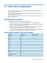
Страница 77: ... must be approved by an acceptable accredited agency responsible for evaluation in the country or region where the power cord set will be used The power cord sets must have a minimum current capacity of 10 amps and a nominal voltage rating of 125 or 250 V AC as required by the power system of each country or region The appliance coupler must meet the mechanical configuration of an EN 60 320 IEC 32...

Страница 78: ...and wall plug must bear a T mark and registration number in accordance with the Japanese Dentori Law The flexible cord must be Type VCT or VCTF 3 conductor 1 00 mm conductor size The wall plug must be a two pole grounding type with a Japanese Industrial Standard C8303 7 A 125 V configuration 4 The flexible cord must be Type RVV 3 conductor 0 75 mm conductor size Power cord set fittings appliance c...

Страница 79: ...he battery in general household waste Follow the local laws and regulations in your area for battery disposal HP encourages customers to recycle used electronic hardware HP original print cartridges and rechargeable batteries For more information about recycling programs see the HP Web site at http www hp com recycle 69 ...

Страница 80: ...7 spare part numbers 18 47 display components 4 display panel removal 48 spare part numbers 18 49 display panel cable removal 53 spare part numbers 19 53 display panel product description 1 display switch 4 DVD RW Drive spare part number 20 E esc key 6 Ethernet product description 1 F fan removal 37 spare part number 16 37 feet removal 26 spare part number 17 26 fingerprint reader 6 fingerprint re...

Страница 81: ...microphone 1 operating system 2 pointing device 2 ports 2 power requirements 2 processors 1 product name 1 security 2 serviceability 2 solid state drive 1 video 1 wireless 1 2 product name 1 R recover options 63 recovery discs 62 64 HP Recovery Manager 63 media 64 starting 64 supported discs 62 system 63 USB flash drive 64 using HP Recovery media 62 recovery media creating 61 creating using HP Rec...

Страница 82: ...nents 8 TouchPad zone 8 U USB 3 0 port 9 10 V vents 11 video product description 1 W webcam 4 webcam light 4 webcam microphone module removal 50 spare part numbers 18 50 Windows system restore point 61 62 Windows key 6 Windows tools using 62 wireless antenna location 4 removal 52 spare part numbers 19 53 wireless product description 1 2 WLAN antenna location 4 removal 52 spare part numbers 19 53 W...

Отзывы: