HP 10642 rack Скачать руководство пользователя страница 8

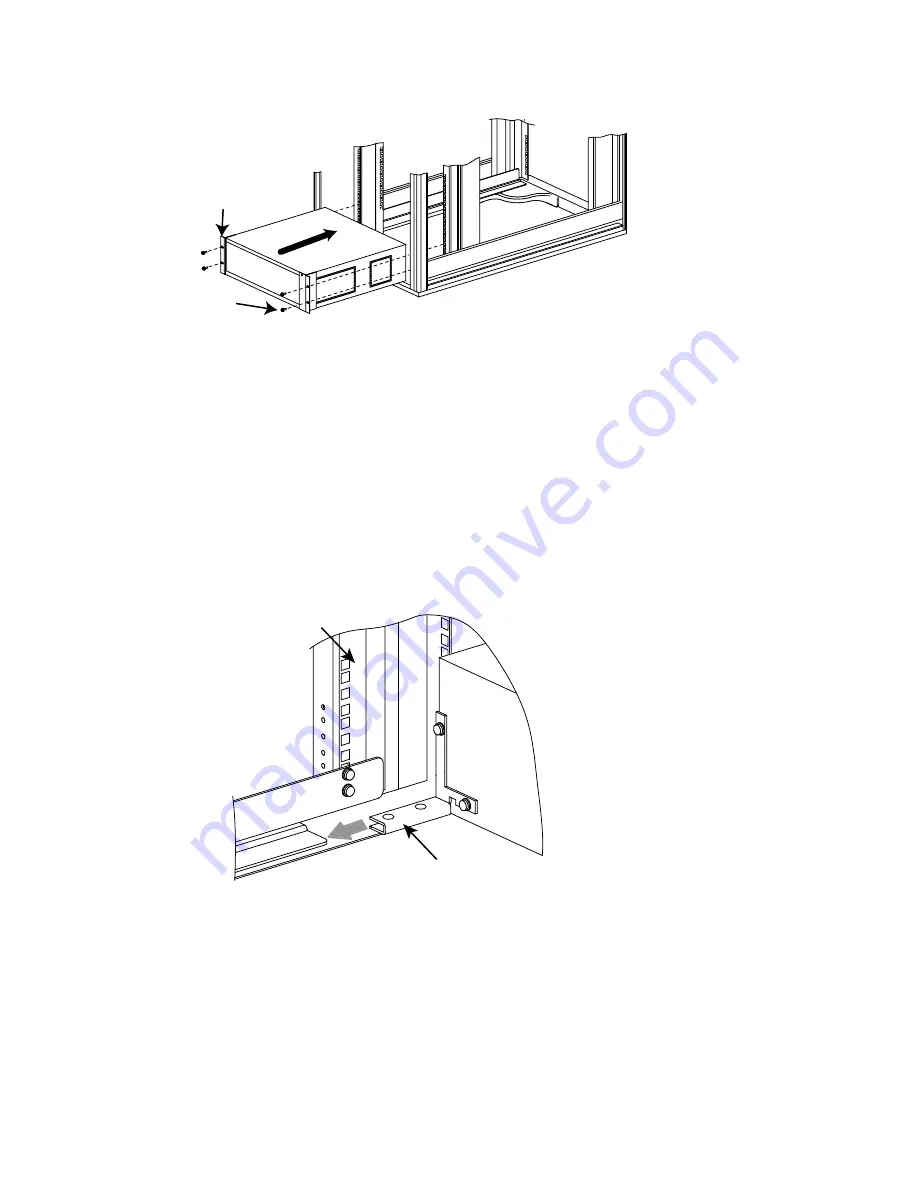
Figure 5: Inserting the Interconnect Chassis into the Rack

Rear of Rack

X

Y

1.

Locate and mark the rear column mounting locations as follows:

a.

To attach the bracket to a 5U (9-slot, 64-port) interconnect, position the
fasteners at locations 1-middle and position 5-middle.

b.

To attach the bracket to a 3U (5-slot, 32-port) interconnect, position the
fasteners at locations 1-middle and position 3-middle.

2.

Insert an M6 cage nut into the back of the rack at each fastener location,
using a total of four cage nuts.

3.

Lift and align the interconnect so that the retainer brackets are level and
square with the rails, as shown in Figure 6.

Figure 6: Aligning the Retainer Bracket with the Rail

Rear Right Rack
Column

Left Retainer Bracket

4.

Slide the interconnect chassis in until its front brackets stop against the rear
rack columns. (Callout 1 in Figure 5 identifies the left front bracket.)

5.

Using a #2 Phillips screwdriver and two M6 x 16-mm pan-head screws per
bracket, secure each front bracket to the cage nuts that are mounted on the
rack columns (see callout 2 in Figure 5). Use a total of four screws and
tighten the screws to their specified torque.

10 Securing the Chassis to the Rail

Working at the front of the rack, secure the interconnect chassis to the rail, as
shown in Figure 7.

Myrinet Interconnect Rack Kit Installation Guide

Содержание 10642 rack

Страница 1: ...install the Myrinet interconnect rack kit into an HP Cluster Platform using the HP Model 10642 rack This kit is designed to support a Myrinet interconnect with a 3U 5 slot chassis or a 5U 9 slot chassis Larger models of Myrinet interconnect require a different kit with a ventilating baffle Hewlett Packard Company Palo Alto California ...

Страница 2: ...ice The only warranties for HP products and services are set forth in the express warranty statements accompanying such products and services Nothing herein should be construed as constituting an additional warranty HP shall not be liable for technical or editorial errors or omissions contained herein Printed in the U S A ...

Страница 3: ... hp com linux onlinedocs 4807 index html 3 Verifying the Kit Contents The kit contains the following components A pair of rails that you mount on the columns of the rack A pair of left and right retainer brackets that you mount on the Myrinet chassis These brackets slide onto the rails The fasteners as specified in Table 1 Table 1 Rail Kit Fasteners Qty Size Type Torque Description 12 M6 x 16 mm M...

Страница 4: ...ct chassis Figure 1 Rail 1 2 4 2 Retainer Brackets The retainer brackets are shown in Figure 2 Figure 2 Retainer Brackets X Y 3 Right Retainer Bracket Left Retainer Bracket When attaching the brackets be aware that their designation of left and right is in reference to their location on the rear of the switch chassis not in reference to the rack columns Figure 2 shows the following details which a...

Страница 5: ... columns At each rack location there are three square mounting holes which are identified as top middle and bottom A fastener location is specified as 10 middle meaning the middle hole of rack position 10 The installation location depends on the configuration rules for your cluster See Section 2 for information about where you can obtain documentation resources Each component occupies a specific r...

Страница 6: ... 1 Phillips screwdriver secure the rail to the rack columns with a M6 x 16 mm pan head screw 4 Repeat steps 1 3 for the right rail 8 Installing the Retainer Brackets Attach the retainer brackets to the interconnect chassis as shown in Figure 4 _______________________ CAUTION _______________________ Use only the specified screws Screws that are too long might penetrate the switch chassis and damage...

Страница 7: ... 2 The elongated hole in the middle of the bracket 2 Use a 1 Phillips screwdriver to secure the retainer bracket to the interconnect chassis with 2 6 32 x 375 in Phillips screws 3 Repeat steps 1 and 2 for the right retainer bracket 9 Inserting the Chassis Into the Rack You insert the interconnect chassis from the rear of the rack with its front panel the connection ports facing the rear of the rac...

Страница 8: ...ackets are level and square with the rails as shown in Figure 6 Figure 6 Aligning the Retainer Bracket with the Rail Rear Right Rack Column Left Retainer Bracket 4 Slide the interconnect chassis in until its front brackets stop against the rear rack columns Callout 1 in Figure 5 identifies the left front bracket 5 Using a 2 Phillips screwdriver and two M6 x 16 mm pan head screws per bracket secure...

Страница 9: ...t the power cable at the rear of the interconnect chassis 2 If necessary mark the high speed network cables to ensure that they can be reconnected to their respective ports 3 Disconnect and remove each high speed network cable bundle until all ports are unplugged Secure the cables out of the interconnect s removal path 4 Depending on whether you are performing a complete disassembly or only replac...

Страница 10: ...ct chassis is to be remounted or if it is replaced Use only the 6 32 x 375 in Phillips pan head screws to attach the retainer brackets to the chassis Use of incorrect screws might damage internal components 8 Myrinet Interconnect Rack Kit Installation Guide ...

Отзывы: