


5
ISRB-2009, Rev. 02_17.
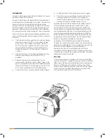
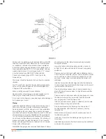
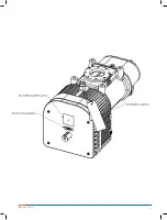
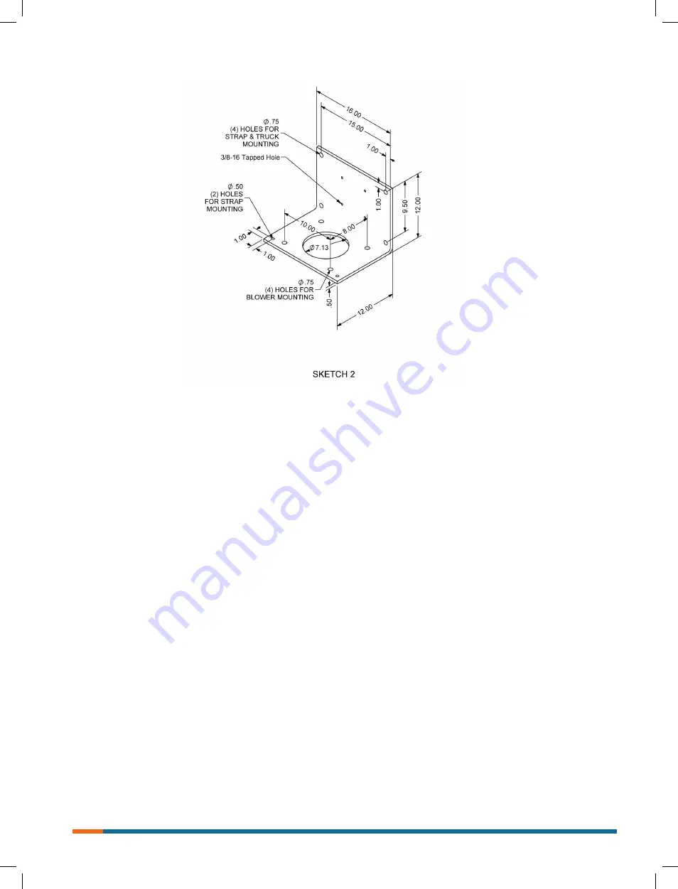
Bottom inlet, top discharge is standard orientation with CCW
rotation on input drive shaft. Blower can be mounted either
on roadside or curbside of truck chassis. Exact installation
instructions cannot be given because of the variety of truck
chassis available. See SKETCH 1 for basic details. Units are
typically held in place on truck chassis by use of “L” shaped
mounting bracket; see SKECH #2 for basic details.
Check output speed range of PTO. It must be for the
blower range.
The blower should be parallel to the truck frame to minimize
vibration.
The PTO shaft must be within the manufacturer’s angularity
limits, not to exceed 5 degrees in the horizontal plane and
3 degrees in the vertical plane.
Brace mounting securely to reduce vibration.
Be sure air filter, oil level gauge, gear case breather and oil
drain plug is not obstructed for normal maintenance.
Do not weld on the blower or base, bearings can be damaged
by the passage of current.
Piping
Install an adequate air filter on blower inlet. Servicing the air
filters is one the most important maintenance operations.
Servicing frequency of filter elements is not time predictable
and must be by the user, depending on dust and moisture
conditions but pressure drop shall never exceed 20” (508 mm)
of water before servicing. Dry filter element life is typically 50
to 300 hours before replacement is necessary. Only replace,
do not reuse dry filter elements via cleaning. Do not allow oil,
grease or solvents to contact the element. Do not operate
blower with damaged filter seals or element. Do not operate
blower without filter element.
WARNING: All piping and accessories downstream of blower
should be rated for the internal pressures being subjected
during full operation.
Insure that inlet and discharge piping are clear, clean and
air tight. Do not allow dirt to enter the blower during piping
operations.
Pressure service, install an air relief valve in discharge line as
close to blower as possible. Vacuum service, install an air relief
valve in inlet line as close to blower as possible. Do not use
any caps, covers, plugs or valves between the blower and
relief valve.
Install a check valve in the discharge line after the relief valve
to prevent back flow of material into the blower and to prevent
reverse rotation of the blower.
Provide a discharge bypass valve to the atmosphere for air
bleed off to lower pressure when too high blower speed thus
flow is present.
Pressure service, install an accurate pressure gauge at or near
the blower discharge. Vacuum service, install an accurate
vacuum gauge at or near the blower inlet.
Install an accurate vacuum gauge or indicator at inlet so able
measure pressure drop across inlet filter.
Provide an adequate sized discharge line. Use as few of
bends as possible; when bends are necessary, use long
radius bends.
Make provisions in piping to allow for expansion as near to
the blower as possible.
Use a dust cover at the final discharge opening when hose
is removed.
Install discharge silencer after the check valve when additional
noise reduction is required.
Содержание Roots 412 HPT
Страница 1: ...www howden com Roots 412 HPT Blower Installation Operation Maintenance Manual...
Страница 11: ...11 ISRB 2009 Rev 02_17...
Страница 12: ...ISRB 2009 Rev 02_17 12...
Страница 13: ...13 ISRB 2009 Rev 02_17...
Страница 14: ...ISRB 2009 Rev 02_17 14...
Страница 15: ...15 ISRB 2009 Rev 02_17...


