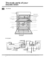
background image

GB

5

PLEASE PHONE US TO REGISTER YOUR APPLIANCE  AND ACTIVATE YOUR PARTS GUARANTEE ON 08448 24 24 24

Installation

Electrical Requirements

For your own safety, we recommend that your cooker 
is installed by a competent person such as one who is 
registered with NICEIC (National Inspection Council for 
Electrical Installation Contracting). The cooker should 
be installed in accordance with the latest edition of the 
IEE Regulations.

Warning: This appliance must be earthed.

Electrical Connections

The installer must check that the voltage shown on 
the rating plate corresponds with the house electricity 
supply. The cooker must be supplied via a suitable 
double pole isolating switch, having a contact 
separation of at least 3mm in all poles placed in a 
readily accessible position adjacent to the cooker. If 
the cooker is to be wired into a connector unit, this 
may be positioned behind the cooker providing the 
following requirements are met:

i)  The connector unit must not project from the wall 

more than 25mm.

ii)  The top of the connector must not be more than 

130mm above floor level.

Remove the terminal cover at the rear base of the 
cooker. Pass the cable through the cable clamp and 
connect to the appropriate terminals provided.
Allow sufficient cable for any future servicing.
Tighten the screws on the cable clamp and replace the 
cover. Make main connections in the connector unit or 
cooker control unit. This appliance conforms to B.S. EN 
55014 regarding suppression of Radio and Television 
reception interference.
A double Pole control switch having a minimum rating 
of 32 amps should be used to feed the cooker using 
a suitably rated cable. Where a hob is fitted adjacent 
to or over the cooker, a 45 amp Double Pole control 
switch should be used to feed both units via separate 
suitably rated cables.
We recommend a minimum of 4mm2 PVC insulated 
twin and earth cable conforming to B.S. 6004 for 
connection of each appliance.

In all cases adhere to routing details (see fig. 4).

This appliance must not be installed over any other 
appliance that generates heat such as a plinth heater.

Note: Due to many different types of installation, a 
mains cable is not supplied with this product. The 
installer will fit the correct type and length of cable.

Important

It is essential that the lower cupboard is constructed 

in the manner illustrated i.e. having side, back, and 
roof panels so joined as to provide no apertures which 
could permit access to the oven unit when installed.

1. General

The appliance is designed for mounting at a safe level 
into an oven housing which must be secured to the 
backing wall.

2. Ventilation

a.  The oven housing unit cabinet dimensions must 

comply with fig. 4.

b.  An air gap of 50mm minimum must be provided at 

the rear of any top or bottom cupboards or shelves 
(see fig. 1).

c.  It is necessary that the cabinets are provided with 

unobstructed ventilation, i.e. from adjacent cabine-
try. This can be done by either raising the base of 
the cabinets using the adjusting feet (or spacers) 
or alternatively by providing a slot in the cabinet 
plinth to the dimensions in fig. 1.

d.  The air gap at rear allows the warmed air to pass out 

of the inner cabinet space. Where it is intended to fit 
cupboards above the oven unit to ceiling height, it is 
essential that the warmed air is exhausted through 
the front of the cabinet (see fig. 1).

e.  If an oven unit is installed adjacent to a tall cabinet, 

steam escaping from the oven when the door is 
opened could condense on and maybe stain the 
adjacent surface. To prevent permanent staining, 
the adjacent surface should be made of a material 
that is heat resisting and easy to clean. Adjacent 
tall cabinets should not be deeper than the oven 
housing cabinet.

3. Final Installation

a.  Using a spirit level, check that the housing cabinet 

is level from side to side and from front to back in 
its installed position.

b.  Correct any unevenness by placing spacers under 

the bottom of the cabinet. Make sure that the cabi-
net rests firmly on the floor without rocking.

c.  Before the oven is fitted, the cabinet must be firmly 

secured to the backing wall for stability.

d.  The oven unit should now be lifted (this is a two 

person lift) into the cabinet and pushed fully home.

e.  Finally, the oven is secured to the cabinet by means 

of the four Phillips C/SK Head screws - two through 
each side trim.

f.  Remove all packaging material from the grill and 

oven interior.

List of loose items:

4 x Phillips C/SK Head No. 6 x 25mm screws.

Содержание DX 1032 CX S

Страница 1: ...ion 5 Tall Cabinet Ventilation 6 The main parts of your Double Oven 8 Start up and use 9 The Cooking Modes in your Double Oven 11 Solarplus Grill 14 Top Oven Conventional Cooking 16 Top Oven Temperatu...

Страница 2: ...t be made by children without supervision Do not use harsh abrasive cleaners or sharp metal scrapers to clean the oven door glass since they can scratch the surface which may result in shattering of t...

Страница 3: ...help remove the new smell heat up the empty ovens to maximum temperature for a minimum of two or three hours keeping the oven doors closed Ensure that the room is well ventilated e g open a window or...

Страница 4: ...the preparation of food in accordance with the instructions outlined in this booklet Any other use of the appliance e g for heating the room constitutes improper use and is dangerous The manufacturer...

Страница 5: ...allation a mains cable is not supplied with this product The installer will fit the correct type and length of cable Important It is essential that the lower cupboard is constructed in the manner illu...

Страница 6: ...4 Tall Cabinet Ventilation Ventilation Slot required here if cabinet does not fit to ceiling 51mm x 457mm min area Ventilation Slot required here if the cabinet does not fit to the ceiling 51mm x 457m...

Страница 7: ...595mm 561mm 562mm 870mm 882mm 870mm if cooker trim is to overlap top edge of shelf excluding pipe work and other projections 4mm2 Cable To Oven Connector Box Fig 4 Fig 2 550mm 550mm min 562mm Viewed...

Страница 8: ...ight Grill Pan Food Support Inner Door Glass Oven Shelves Main Oven Door Door Switch MODEL SERIAL NUMBER LABEL Record the Model No and the Serial No on back page Inner Door Glass Control Panel DURATIO...

Страница 9: ...he button 4 Repeat the above process to set the minutes If a blackout occurs it will be necessary to reset the clock If the icon flashes on the display this indicates that the clock has not been set c...

Страница 10: ...can be used to switch ons witch off the light at any time Do not use the oven lamp as for ambient lighting Residual heat indicators The appliance is fitted with a residual heat indicator When the oven...

Страница 11: ...perfect result every time automatically These values are set using the C O P Programmed Optimal Cooking system The cooking cycle stops automatically and the oven indicates when the dish is cooked You...

Страница 12: ...ooled completely FISH mode Use this function to cook fish with a maximum weight of 1 kg The paper foil package can be placed directly on the dripping pan Place the food inside the oven while it is sti...

Страница 13: ...splay begin to flash 2 Press and hold the buttons to set the desired cooking time 3 Press the button the cooking time will appear on the display 4 Press START STOP button to start cooking 5 When the c...

Страница 14: ...nners are on the top runner position There are two halves to the grill one on the left and one on the right You can choose to have both sides on or just the left side on GRILLING SHOULD NOT BE UNDERTA...

Страница 15: ...nal hooks embrace the edge of the pan fig 1 2 Make sure that the middle part of the handle fits exactly the protruding support of the pan fig 2 and holds the pan from the bottom The food must be place...

Страница 16: ...ration by pressing again the duration button Press start stop button to start the cooking The food to be cooked should be placed in the centre of the shelf with a gap of at least 25mm 1in between it a...

Страница 17: ...mins per 450g 1lb 35 mins over Runner 1 from bottom of oven Beef Lamb foil covered Yes 190 200 35 40 mins per 450g 1lb 20mins Pork slow roasting Yes 170 180 40 mins per 450g 1lb 40 mins over Pork foi...

Страница 18: ...0 190 20 25 Runner 2 from bottom of oven Swiss Roll Yes 200 210 10 15 Runner 2 from bottom of oven Semi rich Fruit cakes Yes 150 160 60 75 7 inch Runner 1 from bottom of oven Rich Fruit cakes Yes 140...

Страница 19: ...a range specific to each cooking mode Telescopic runners and Meat pan The main oven on this cooker comes equipped with telescopic runners meat pan and a food support The meat pan is suitable for cooki...

Страница 20: ...minutes Notes For best results use one shelf Preheat the oven before use COOK CHART Fan oven mode Meat Pre heat Temperature Cooking Time Beef Beef foil covered No Yes 160 180 C 180 190 C 20 25 minutes...

Страница 21: ...CTIVATE YOUR PARTS GUARANTEE ON 08448 24 24 24 Temperature Conversion Chart Gas Mark F Main Conventional Oven Main Fan Oven 250 120 100 1 275 140 120 2 300 150 130 3 325 160 140 4 350 180 160 5 375 19...

Страница 22: ...vy soiling to run the ovens without shelves or meat pan at a maximum setting for a couple of hours Fan Oven mode only It should not normally be necessary to clean the Stayclean panels with water If th...

Страница 23: ...supply to the appliance is switched off and the appliance is fully cold before removing the lamp lens Open the oven door and remove the oven shelves Using a thick cloth grip the lamp lens unscrew ant...

Страница 24: ...inner glass panel may be cleaned while still warm without removing it from the door After cleaning rinse and dry with a soft cloth DROP DOWN DOORS Remove the door inner glass as follows Remove screws...

Страница 25: ...e back on again Reset the timer to the correct time and Manual operation using the instructions given in the timer section of the book Oven temperatures too high or low Check temperature and shelf pos...

Страница 26: ...s not work The oven lamp is not covered by the guarantee The part is easily changed see the section on oven lamp replacement A new lamp may be obtained from our Parts department see back page Draught...

Страница 27: ...resulting from transportation improper use neglect or interference or as a result of improper installation Replacement of any consumable item or accessory These include but are not limited to plugs c...

Страница 28: ...pply a full range of genuine replacement parts as well as accessory products that protect and hygienically clean your appliance to keep it looking good and functioning efficiently throughout its life...

Отзывы: