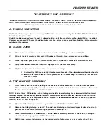
HL6200 SERIES
DISASSEMBLY AND ASSEMBLY
ENSURE APPLIANCE IS DISCONNECTED FROM THE ELECTRICITY SUPPLY BEFORE DISASSEMBLING.
NOTE ALL CONNECTION DETAILS AND ROUTING OF LEADS BEFORE DISASSEMBLING.
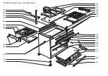
Numbers appearing in the text refer to illustrations and parts list numbers.
A.
SLIDING TABLETOPS
Slide both tabletops open. Remove cover caps 130 and the two screws securing handle 105. Withdraw the handle
from the tabletop assembly.
Slide the tabletop required inwards, past its closed position, until the two plastic sliding blocks 106 on the cabinet
Channels are exposed. Withdraw the sliding blocks from the cabinet channels and then slide the tabletop assembly
out clear of the channels.
B.
GLASS DOOR
1.
Remove the two miniature countersunk screws at each end of the glass door handle 114.
2.
Drill out the rivet securing striker plate 115, using a 2.5mm bit. Use extreme care when drilling.
3.
While supporting glass door 113, remove striker plate 115, handle 114 and inner steel channel 506.
4.
Splay side channel assemblies 509 & 511 slightly and lift the glass door away.
5.
Replace the glass door in reverse order in reverse order ensuring:
I Cushion strips 505 are correctly fitted between the ends of the glass door and the side channels
II Insert 514 is fitted to the hole in the glass door before assembling and inserting a new rivet size
2.4mm x 7.5mm.
C. TOP ELEMENT ASSEMBLY
1.
From inside of cabinet, squeeze locking barbs and release mains lead bush 121 retainer from rear panel.
Remove rear cover strip 510, secured by a single screw, to the extent of the mains lead wires. Disconnect
the top element leads from terminal block 120.
NOTE: Terminal block 120 includes push-in locking terminals for internal wiring. Leads inserted in the front-most
terminals may only be released by inserting a small screwdriver or similar in the slots provided in the front of the
terminal block. Rear-most leads may release with a sharp pull. If leads cannot be released, or are not gripped on
insertion, item 120 must be replaced.
2.
Open the sliding tabletops and remove glass dishes and lids 101 and holders 103.
3.
Remove the sliding tabletops as in A.1. Then slide each tabletop in turn inwards past its closed position to
gain access to the four screws securing top element assembly 107.
4.
Use a powerful magnet or suitable tool to lift the element assembly out clear of the cabinet, feeding the
element wires through grommet 110 in the cabinet.
5.
Refit in reverse order, taking care that the rear cover strip fixing screw is clear of cables when fixing.


