background image

22

Snug the screws, 

but do not tighten.

Sheet Metal Bracket

Overlay Panel

Tighten the screws.

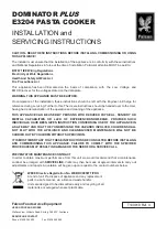
5) Fasten the overlay panel to the door using the four M4×25 pan head screws provided. 

Snug the screws, but do not tighten. See Fig. 24.

6) Fasten the sheet metal bracket to the bottom of the door with the three T2 screws 

provided. Tighten the screws to the door. See Fig. 25.

3) Adjust the sheet metal bracket so that it is flush with the bottom of the door. See Fig. 22. 
4) Remove the overlay panel from the door and tighten the two M4×8 truss head screws 

securing the sheet metal bracket to the overlay panel. See Fig. 23. 

(4) Attachment of Overlay Panel to Door

1) Fasten the sheet metal bracket to the overlay panel using the two M4×8 truss head 

screws provided. 

Snug the screws, but do not tighten. See Fig. 20.

2) Temporarily fasten the overlay panel to the door using 2 of the M4×25 pan head screws 

provided. See Fig. 21.

Sheet Metal Bracket

Door

Sheet Metal Bracket

Screws

Overlay Panel

Door

Screws

Fig. 20

Fig. 21

Overlay Panel

Snug the screws, 

but do not tighten.

Sheet Metal Bracket

Fig. 22

Fig. 23

Fig. 24

Fig. 25

Содержание AM-50BAJ

Страница 1: ...Models AM 50BAJ AM 50BAJ DS AM 50BAJ AD AM 50BAJ ADDS Self Contained Cuber Instruction Manual Issued 9 28 2017 Revised 12 11 2017 hoshizakiamerica com...

Страница 2: ...on is the responsibility of the installer Product failure or property damage due to improper installation is not covered under warranty Hoshizaki provides this manual primarily to assist qualified ser...

Страница 3: ...ter Supply and Drain Connections 26 G Final Checklist 27 III Operating Instructions 28 A Important Notes About Usage 28 B Startup 29 IV Maintenance 31 A Maintenance Schedule 31 B Cleaning and Sanitizi...

Страница 4: ...tions This icemaker requires an independent power supply of proper capacity See the nameplate for electrical specifications Failure to use an independent power supply of proper capacity can result in...

Страница 5: ...ern install in a contained area with a floor drain Install the icemaker in a location that stays above freezing Normal operating ambient temperature must be within 45 F to 100 F 7 C to 38 C If using t...

Страница 6: ...6 I Specifications A Construction Top Panel Ice Making Mechanism Scoop Holder Front Panel Control Switch Louver Bin Control Thermostat Bulb Slope Magnet Catch Door Power Cord...

Страница 7: ...the nameplate We reserve the right to make changes in specifications and design without prior notice Model Number AM 50BAJ AM 50BAJ DS AM 50BAJ AD AM 50BAJ ADDS AC Supply Voltage 115 120 60 1 Amperes...

Страница 8: ...8 C Dimensions Connections 1 AM 50BAJ Units mm in...

Страница 9: ...9 2 AM 50BAJ DS Units mm in...

Страница 10: ...10 3 AM 50BAJ AD Units mm in...

Страница 11: ...11 4 AM 50BAJ ADDS Units mm in...

Страница 12: ...with the voltage specified on the nameplate B Location 1 General This icemaker is approved for indoor or outdoor use NOTICE Normal operating ambient temperature must be within 45 F to 100 F 7 C to 38...

Страница 13: ...mm minimum 24 610 mm minimum AM 50BAJ AD AM 50BAJ ADDS 32 814 mm minimum AM 50BAJ AM 50BAJ DS Min 34 864 mm AM 50BAJ AD AM 50BAJ ADDS Min 32 814 mm Min 15 381 mm Between Two Cabinets Between a Cabine...

Страница 14: ...move the door from hinge A See Fig 1 3 Remove hinge A and the bracket from the right side of the unit and the top brace from the left side Rotate hinge A to position the gasket notch to the inside the...

Страница 15: ...ront with the 2 screws removed in step 2 6 Remove the 2 screws attaching the door handle and also remove the other 2 screws indicated in the illustration Use 2 of the screws to attach the handle to th...

Страница 16: ...uality results 1 Parts Ensure that all parts required for the overlay panel assembly are contained in the accessories bag Overlay Panel Parts No Description Part Number Qty 1 Threaded Wood Insert 4A40...

Страница 17: ...ADDS and the directions that follow to prepare your overlay panel a AM 50BAJ DS AM 50BAJ DS Overlay Panel Specification Overlay Panel Height 29 17 32 750 mm Overlay Panel Width 14 13 16 376 mm Overla...

Страница 18: ...Panel Specification Overlay Panel Height 27 9 16 700 mm Overlay Panel Width 14 13 16 376 mm Overlay Panel Thickness 5 8 16 mm minimum 3 4 19 mm maximum Overlay Panel and Door Weight total 20 lb 9 kg...

Страница 19: ...m of the door slightly and gently remove the door from hinge A See Fig 10 If you are leaving the door right hinged skip to step 7 If you would like to reverse the door swing proceed to step 6 3 Fabric...

Страница 20: ...he front with the 2 screws removed in step 6b 6 If you would like to reverse the door swing do the following a Contact your local distributor to purchase Hoshizaki Kit HS 0229 The kit contains hinge A...

Страница 21: ...extend over the overlay panel See Fig 19 7 Remove the bushings from hinge C1 and hinge C2 the hinges attached to the door See Fig 16 8 Remove the gasket from the door See Fig 17 Gasket Screws Mark the...

Страница 22: ...ee Fig 22 4 Remove the overlay panel from the door and tighten the two M4 8 truss head screws securing the sheet metal bracket to the overlay panel See Fig 23 4 Attachment of Overlay Panel to Door 1 F...

Страница 23: ...attached to the door See Fig 27 Canoe Clips Fig 26 Tighten the screws Bushing Bushing Gasket Fig 27 9 Attach the door to hinge A then continue to maintain a hold on the door Screw the hinge stop pin...

Страница 24: ...feet 3 Insert the 4 canoe clips included in the accessory bag into the upper and lower holes on the inside of the door opposite from the door handle See Fig 30 These holes are provided to allow for do...

Страница 25: ...the power cord and do not use an adapter plug Failure to follow these instructions may result in death electric shock or fire Do not use an extension cord To reduce the risk of electric shock make su...

Страница 26: ...ter hammer can cause icemaker damage that may lead to water leakage or flooding If using the optional drain pump HS 5061 test its operation every time the icemaker is cleaned and sanitized See IV E Op...

Страница 27: ...klist WARNING CHOKING HAZARD Ensure all components fasteners and thumbscrews are securely in place after installation Make sure that none have fallen into the ice storage bin 1 Is the icemaker level 2...

Страница 28: ...aning and sanitizing may be required in some water conditions Wash your hands before removing ice Use the plastic scoop provided This appliance is not intended for use by persons including children wi...

Страница 29: ...ng the Icemaker for Periods of Non Use Keep ventilation openings in the appliance enclosure or in the built in structure clear of obstruction Do not place objects on top of the icemaker The ice storag...

Страница 30: ...ose fitting may cause a water leak 8 Clean the ice storage bin liner door liner and door gasket using a neutral cleaner Rinse thoroughly after cleaning 9 Move the control switch to the ICE position to...

Страница 31: ...enance Schedule The maintenance schedule below is a guideline More frequent maintenance may be required depending on water quality the icemaker s environment and local sanitation regulations Maintenan...

Страница 32: ...warm water This is a minimum amount Make more solution if necessary IMPORTANT For safety and maximum effectiveness use the solution immediately after dilution 2 Cleaning Procedure 1 Remove all ice fro...

Страница 33: ...teps 9 through 12 three more times to rinse thoroughly 3 Sanitizing Solution Dilute 0 5 fl oz 14 8 ml or 1 tbs of a 5 25 sodium hypochlorite solution chlorine bleach with 1 gallon 3 8 l of warm water...

Страница 34: ...ucing Pipe Rail Rail Fig 43 Fig 44 Discharge Tube Spray Assembly Fig 41 Fig 42 Right Bracket Left Bracket Caps Discharge Tube Caps 9 Soak all of the removed parts and the scoop in the sanitizing solut...

Страница 35: ...tizing solution 19 Mix a new batch of the sanitizing solution and slowly pour it into the water tank 20 Move the control switch to the WASH position 21 After circulating the sanitizing solution for 15...

Страница 36: ...eading to costly water damage 1 Move the control switch to the OFF position WARNING To reduce the risk of electric shock do not touch the control switch with damp hands 2 Remove all ice from the ice s...

Страница 37: ...the louver and front panel in their correct positions Ensure that the screws are securely in place 6 Plug the icemaker back in Move the control switch to the ICE position to start the automatic icemak...

Страница 38: ...rage bin then completely restrict the discharge hose while the drain pump is operating See Fig 50 Pour more water into the icemaker s ice storage bin until the icemaker turns off The drain pump will c...

Страница 39: ...ures follow the instructions below to reduce the risk of costly water damage 1 Close the water supply line shut off valve then open the water supply line drain valve See Fig 31 2 Allow the line to dra...

Страница 40: ...osal This icemaker contains refrigerant and must be disposed of in accordance with applicable national state and local codes and regulations Refrigerant must be recovered by properly certified service...

Страница 41: ...41 618 Hwy 74 South Peachtree City GA 30269 USA P 770 487 2331 F 770 487 3360 hoshizakiamerica com 1A4925 011...

Отзывы: