J1
J1
Disattivata - Disabled
1
1
2
2
3
3
4
4
J5
J5
1
1
2
2
3
3
4
4
Attivata - Enabled
J3
J4
1
2
3
1
2
3
Attivato con luci bianche di testa
Enabled together with white head lights
Attivazione indipendente (motrice AUX1, folle AUX2)
Independent command (motor car AUX1, dummy AUX2)
J3
J4
1
2
3
1
2
3
Disattivato
Disabled
PCB Unità motrice
Motor unit PCB
PCB Unità motrice
Motor unit PCB
PCB Unità motrice
Motor unit PCB
PCB Unità motrice
Motor unit PCB
PCB Unità motrice
Motor unit PCB
PCB Unità folle
Dummy unit PCB
PCB Unità folle
Dummy unit PCB
PCB Unità folle
Dummy unit PCB
PCB Unità folle
Dummy unit PCB
PCB Unità folle
Dummy unit PCB
J3
J4
J4
J5-2
J5-1
1
2
3
1
2
3
SOLO per funzionamento digitale in sistemi a 2 rotaie
Digital running on 2-rails systems ONLY
J2
J3
J1-1
J1-2
1
1
1
1
1
3
3
4
2
2
2
2
2
Motor unit PCB
Dummy unit PCB
4
4
5
3
3
3
6
Predisposizione per l’altoparlante
Speaker predisposition
1
2
3
4
DIGITALIZZAZIONE - DIGITAL
IMPOSTAZIONE PONTICELLI - JUMPER SETTINGS
Terzo faro frontale - Third head light (Jumpers J3 - J4)
Presa di corrente selettiva (solo funzionamento analogico su sistemi a 2 rotaie)
Selective electric pick-up (analog running on 2-rail systems only) - Jumpers J1-J5
È
possibile congurare il terzo faro frontale per le seguenti modalità di funzionamento.
It’s possible to configure the third front head light for the following working modes.
Questo modello
è
predisposto
per ricevere
un decoder digitale
con
interfaccia
21 poli 21MTC/NEM
660.
Per
installare
il
decoder procedere
come
segue:
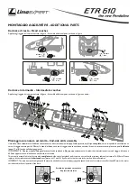
1)
Rimuovere
il coperchio
sul
tetto
dell’unità
motrice
(vedi gura) facendo leva sulla parte anteriore
con
un
piccolo
cacciavite;
2)
Rimuovere la nta presa, necessaria
nel
funzionamento analogico,
per
accedere alla spina
21
poli;
3)
Installare
il
decoder
21 poli
sulla spina, prestando particolare attenzione al suo
corretto
orientamento;
4)
Riposizionare
il coperchio
sul
tetto
dell’unità motrice.
Nel
caso
si
desideri installare un decoder
con
funzionalità sonore, l’altoparlante può
essere
posizionato nella sede prevista nella parte
posteriore
dell’arredo
interno
dell’unità motrice, a cui
si
può accedere smontando la carrozzeria (vedere pagina successiva).
This model
is
ready
to receive
a digital decoder with
21-poles 21MTC/NEM 660
interface.
To
install a digital decoder please proceed as follows:
1) Remove
the
cover on
motorized
unit’s
roof
,
near the driver
’s
cab, pushing
on
the front part with a small screwdriver;
2) Remove
the «false plug», necessary
in
analog running, from the
21-poles
plug;
3)
Install the digital decoder
on
the
21-poles
plug, with particular attention
to its correct
orientation;
4) Put
the roof
’s cover
back
to its
place.
In
case of installation of a digital decoder with Sound functions, the speaker
must be
placed
in its
housing
present in
the rear side of
interiors
of the
motorized
unit,
that can
be
accessed
by
removing the bodyshell
(see
following page).
Il
circuito stampato
presente nelle
due unità di testa comprende alcuni
ponticelli che permettono
di
congurare diverse funzionalità
elettriche
del modello.
Per
accedervi
è
necessario rimuovere
il coperchio
presente
sul
tetto vicino
alle cabine di guida.
The printed
circuit
board
in
the two head
units
includes
jumpers
that allow
to
configure different
electric
features
of the model.
To
access the
PCB it’s
necessary
to remove
the
cover on
the roof
,
near the two driver
’s
cabs.
IMPORT
ANTE:
Nel
funzionamento digitale
e/o in sistemi
a
3
rotaie
questa funzionalità deve
essere sempre
disattivata.
IMPORTANT
:
In
digital running and/or
on
3-rail
systems
this feature
must
always
be set
as disabled.
Questa funzione
consente
al modello di captare la
corrente
solamente dall’unità di testa,
con
commutazione automatica
in
base al
senso
di marcia.
This feature allows the model
to
pick
up
the
electric current only
from the head coach, with automatic switch related
to
the running direction.


