Horizon Hobby E-flite Carbon-Z Cub SS Скачать руководство пользователя страница 14

EN

Carbon-Z Cub SS

14

SAFE

®

 Select Switch Designation 

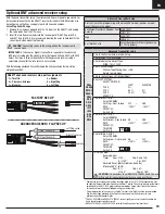
This aircraft includes Spektrum Smart Technology in the ESC and receiver, which 

can provide telemetry information like battery voltage and ESC temperature. To 

take advantage of Smart Technology, you will need a compatible transmitter. A 

firmware update for your transmitter may be required.

To access all of the available features of Smart Technology, use Spektrum Smart 

batteries to power this aircraft. In addition to ESC data, Spektrum Smart batteries 

can communicate detailed battery data through the Smart Technology system.

To View Smart Telemetry:

1.  Begin with the transmitter bound to the receiver
2.  Power on the transmitter.
3.  Power on the aircraft.
4.  The Smart Logo appears under the battery logo on the home page. A signal bar 

appears in the top left corner of the screen.* 

5.  Scroll past the servo monitor to view Smart technology screens. 

* If the transmitter that you intend to use with this aircraft is not displaying 

telemetry data, visit spektrumrc.com and update your firmware. With the latest 

firmware installed on your transmitter the telemetry option should now be 

functional on your transmitter. 

For more information about compatible transmitters, firmware updates, and how to use 

the Smart Technology on your transmitter, visit spektrumrc.com.

Smart Technology™ Telemetry

Once SAFE Select is enabled, you can choose to fly in SAFE mode full-time, or 

assign a switch. Any switch on any channel between 5 and 9 can be used on your 

transmitter. 

TIP

: If model has a reversing ESC feature, aux2 is not available for safe select.

If the aircraft is bound with SAFE Select disabled, the aircraft will be in AS3X mode 

exclusively.

CAUTION:

 Keep all body parts well clear of the propeller and keep the 

aircraft securely restrained in case of accidental throttle activation.

IMPORTANT:


To be able to assign a switch, first verify: 

•  The aircraft was bound with SAFE Select enabled.
•  Your choice for the SAFE Select switch is assigned to a channel between 

5 and 9 (Gear, Aux1-4), and travel is set at 100% in each direction.

•  The aileron, elevator, rudder and throttle direction are set to normal,  

not reverse.

•  The aileron, elevator, rudder and throttle are set to 100% travel. If dual 

rates are in use, the switches need to be in the 100% position.

See your transmitter manual for more information about assigning a switch to a channel.

TIP: 

If a SAFE Select switch is desired for your 6 function aircraft, and you are 

using a 6 channel transmitter, the SAFE Select switch channel will have to be 

shared with either channel 5 or 6 of the transmitter. This does not apply to the NX6. 

Please refer to your NX6 instruction manual for further details.

Assigning a Switch

1.  Power on the transmitter.
2.  Power on the aircraft.
3.  Hold both transmitter sticks to the inside bottom corners, and toggle the desired 

switch 5 times quickly (1 toggle = full up and down). 

4.  The control surfaces of the aircraft will move, indicating the switch has been 

selected.

Repeat the process to assign a different switch or to deactivate the current switch. 

Mode 1 and 2 transmitters

X 5

100%

100%

Assigned Switch

This example of the channel monitor shows the stick positions for assigning a 

switch, the switch selection on Aux3, and +/- 100% travel on the switch.

SAFE Select Switch Assignment Stick Positions

TIP:

 Use the channel monitor to verify channel movement.

RPM:

Volts:

Motor:

Throttle:

Fet Temp:

BEC:

0

0.0V

0.0A   

0% Output

0%

0.0C

0.0C   

0.0A     0.0V

Monitor

THR

-100

AIL

100

ELE

-100

RUD

-100

GER

-100

AX1

-100

AX2

AX3

-100

AX4

-100

+/-100

Содержание E-flite Carbon-Z Cub SS

Страница 1: ...Instruction Manual Bedienungsanleitung Manuel d utilisation Manuale di Istruzioni Carbon Z Cub SS SAFE Select Technology Optional Flight Envelope Protection ...

Страница 2: ...ings in the manual prior to assembly setup or use in order to operate correctly and avoid damage or serious injury As the user of this product you are solely responsible for operating in a manner that does not endanger yourself and others or result in damage to the product or the property of others Always keep a safe distance in all directions around your model to avoid collisions or injury This m...

Страница 3: ...ch Quick Start Information Transmitter Setup 1 Blank Acro Model 2 Wing Type 1 Aileron 1 Flap 3 Servo Reversing Gear Reversed All Others Normal 4 Travel Adjust All Surfaces 100 Dual Rates High Rate Low Rate Aileron p 50mm q 45mm p 35mm q 30mm Elevator p 42mm q 42mm p 30mm q 30mm Rudder 65mm 65mm 50mm 50mm Flap Travel Take off q 20mm Landing q 35mm EXPO Soft center High Rate Low Rate Aileron 10 5 El...

Страница 4: ...DX9 DX10t DX18 DX20 iX12 iX20 NX6 NX8 and NX10 Start all transmitter programming with a blank ACRO model do a model reset then name the model Set Aileron Eleva tor and Rudder Dual Rates to HIGH 100 LOW 70 Set Servo Travel to 100 Set Throttle Cut to 130 DX6i 1 Go to the SETUP LIST MENU 2 Set MODEL TYPE ACRO 3 Go to ADJUST LIST MENU 4 Set FLAPS Norm 100 Flap Elev 0 LAND 100 Flap Elev 15 DX7S DX8 1 G...

Страница 5: ...legs with the holes of the landing gear bracket Secure the landing gear into place using 2 screws F and 2 nuts G Repeat installation for opposite strut 4 Connect both hooks H to the holes located on the strut behind the tire 5 Align the bottom of the landing gear suspension spring I to the second hole of the front landing bracket Secure it into place with the screw F and nut G Repeat installation ...

Страница 6: ...d the hinges by turning the rudder left then carefully apply thin CA to each hinge in the right side of each slot Repeat this process for the left side of the rudder Apply 4 5 drops on each hinge on each side 5 Connect the ball link D to the rudder control horn s middle hole E using a screw F and nut G Ensure the rudder servo arm is in the correct position then adjust the ball link on the linkage ...

Страница 7: ...oles in the bottom of the horizontal tail 4 Attach the ball link C to the elevator control horn s middle hole using the included nut D and screw E 5 Ensure the elevator servo arm is in the correct position then adjust the linkage to center the elevator When needed disassemble in reverse order TIP Use needle nose pliers or ball link pliers RVO1005 to remove or install a link on a control horn A C B...

Страница 8: ...rom the motor for correct propeller operation Ensure the nut holds the propeller tightly without damaging the propeller 6 Install the spinner M on the collet using the screw N Disassemble in reverse order Not all wiring shown NOTICE If the propeller is not balanced the aircraft may vibrate causing the stabilization system to not operate correctly and or decrease the life of the servos Horizon Hobb...

Страница 9: ...tighten lock nuts on the screws Ensure the vertical brackets can pivot freely on the wing mounts 3 Install the wide front strut G on the front strut mounts using a screw H and lock nut F 4 Install the narrow rear strut J on the rear strut mount using a screw H and lock nut F TIP DO NOT overtighten lock nuts on the screws Ensure the struts can pivot freely in the strut mounts 5 Attach the vertical ...

Страница 10: ... Secure the wings on the fuselage using 4 thumb screws E in the holes on the top of the wings 5 Install the 2 antenna F on top of the two rear thumb screws by pressing them onto the thumb screw 6 Connect the left and right wing struts to the fuselage mounts G using 4 pins H and 4 R clips I Removal We recommend removing the wings from the fuselage for storage or transport of the aircraft TIP Remove...

Страница 11: ...fuselage 2 Attach the appropriate control surfaces servo leads to the their respective ports on the receiver using the table at the right 3 Using double sided servo tape mount the receiver on the receiver platform The receiver should be mounted parallel to the length of the fuselage with the label facing up and the servo ports facing the rear of the aircraft as shown The orientation of the receive...

Страница 12: ... battery compartment that best suits your battery size and weight The battery compartment has multiple positions to lock the battery tray into B as shown Once in place press down on the lock tab to lock the tray into place Adjust as needed to acquire proper CG See the Adjusting the Center of Gravity instructions for more information 5 Proceed to the binding section if the receiver is not bound 6 C...

Страница 13: ...all the time or you can assign a switch to toggle between SAFE Select and AS3X modes Thanks to SAFE Select technology this aircraft can be configured for full time SAFE mode full time AS3X mode or mode selection can be assigned to a switch IMPORTANT Before binding read the transmitter setup section in this manual and complete the transmitter setup table to ensure your transmitter is properly progr...

Страница 14: ...in AS3X mode exclusively CAUTION Keep all body parts well clear of the propeller and keep the aircraft securely restrained in case of accidental throttle activation IMPORTANT To be able to assign a switch first verify The aircraft was bound with SAFE Select enabled Your choice for the SAFE Select switch is assigned to a channel between 5 and 9 Gear Aux1 4 and travel is set at 100 in each direction...

Страница 15: ...ections Elevator 1 Pull the elevator stick back The elevators should move up which will cause the aircraft to pitch up 2 Push the elevator stick forward The elevators should move down which will cause the aircraft to pitch down Ailerons 1 Move the aileron stick to the left The left aileron should move up and the right aileron down which will cause the aircraft to bank left 2 Move the aileron stick...

Страница 16: ...Arms Aileron Elevator Rudder Flaps Center of Gravity CG The CG location is measured from the leading edge of the wing at the root This CG location has been determined with the recommended Li Po battery SPMX40006S50 installed in the middle of the battery compartment 105 120mm back from leading edge at the root During your first flight trim the aircraft for level flight at 3 4 throttle with flaps an...

Страница 17: ...ps takeoffs and landings are shorter When taking off the tail will come off the ground quicker for better rudder control during the takeoff roll During landing the flaps allow a landing approach to be steeper with the ability to use more throttle Flaps make the plane come in at a slower airspeed and make it easier to flare and settle in for a smooth landing When deploying the flaps slow the aircra...

Страница 18: ...rection servo must be set to NORMAL with servo travel at 100 for correct operation of the tow release 5 Move the servo arm down using the GEAR switch 6 Remove the screw E and servo arm F from the servo figure 1 7 Install the Z bend of the tow release pin G included with the aircraft in the innermost hole of the arm from the bottom of the servo arm figure 2 8 Install the tow release pin in the tow ...

Страница 19: ... the flap travel to your preference on subsequent flights TRAVEL SUBTRIM and ABSOLUTE TRAVEL varies slightly per aircraft and will need to be fined tuned for your specific aircraft ABSOLUTE TRAVEL in SERVO SETUP is set to limit your flap servos from over travel AR637T advanced receiver setup port assignments 1 Throttle 2 Y harness Ailerons 3 Elevator 4 Rudder 5 Right flap 6 Left flap Advanced Tran...

Страница 20: ... connected to the ESC Extra propeller noise or extra vibration Damaged propeller and spinner collet or motor Replace damaged parts Propeller is out of balance Balance or replace propeller Prop nut is too loose Tighten the prop nut Reduced flight time or aircraft underpowered Flight battery charge is low Completely recharge flight battery Propeller installed backwards Install propeller with numbers...

Страница 21: ...a t Carbon Z Cub SS EFL12423 Tailwheel Carbon Z Cub SS EFL12424 Spinner Orange Carbon Z Cub SS SPMXAE1060B Avian 60 Amp Brushless Smart ESC EFL12425 Battery Tray EFLM7450 BL50 BL Outrunner Motor 525Kv EFLP1570E 15 x 7 Electric Propeller EFLR7145 26g Digital MG Mini Servo EFLR7155 13g Digital Sub Micro Servo SPMAR637T AR637T 6 CH AS3X Telemetry RX Problem Possible Cause Solution Aircraft will not c...

Страница 22: ...tion or misuse no liability shall be assumed nor accepted for any resulting damage or injury By the act of use setup or assembly the user accepts all resulting liability If you as the purchaser or user are not prepared to accept the liability associated with the use of the Product purchaser is advised to return the Product immediately in new and unused condition to the place of purchase Law These ...

Страница 23: ...This equipment generates uses and can radiate radio frequency energy and if not installed and used in accordance with the instructions may cause harmful interference to radio communications However there is no guarantee that interference will not occur in a particular installation If this equipment does cause harmful interference to radio or television reception which can be determined by turning ...

Страница 24: ...ed with permission of Bachmann Industries Inc Cub Crafters Carbon Cub associated emblems and logos and body designs of vehicles are either registered trademarks or trademarks of Cub Crafters Inc and are used with permission Futaba is a registered trademark of Futaba Denshi Kogyo Kabushiki Kaisha Corporation of Japan All other trademarks service marks and logos are property of their respective owne...

Отзывы: