Honeywell Zio TR70 Скачать руководство пользователя страница 3

ZIO

®

/ZIO PLUS LCD WALL MODULES

3

63-2719—03

SETUP AND CONFIGURATION

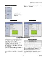
Initial Setup and Configuration

Once the wall module is wired to the controller, you configure 

the wall module using the PC-based, Niagara Workbench 

Tool. Refer to the applicable programmable controller User’s 

Guide. (Refer to the Honeywell Spyder User’s Guide, form 63-

2662, or the ComfortPoint Programmable Controller User’s 

Guide, form 63-2663, depending on the programmable 

controller used.) This tool is used to configure the wall module 

for either the Spyder or the ComfortPoint programmable 

controller.

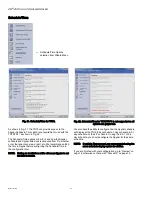
Confirm Bus Address Setting

Check to ensure that the Wall Module’s bus address dial 

(located on the back of the module) is set to match the setting 

in the configuration tool. TR70 models can be set from 1–5 

and TR71/TR75 can be set from 1–10 (0 on the Zio address 

dial is equal to 10 in the configuration tool). The address must 

be different for each device on the Sylk bus. Up to four Zios 

per Spyder are allowed with any combination of TR71/TR75s 

and up to three Zios are allowed if one or more is a TR70 

model.

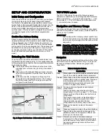
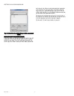
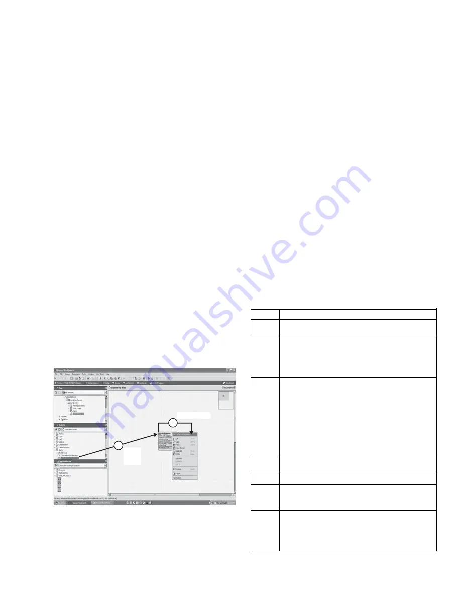
Selecting the Wall Module

You will use the Sylk S-Bus wall module function block from 

the Palette’s Built-In folder (see Fig. 3). This configuration has 

nothing programmed except the room temperature parameter 

and occupancy status.

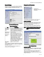
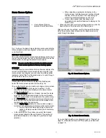
1. Add the Sylk S-Bus Wall Module function block to the 

wire sheet via a left click, drag, and drop. See callout 1 

in Fig. 3.

2. Right click on the S-Bus Wall Module function block to 

open the Configuration Properties menu. See callout 2 

in Fig. 3.

3. Left click on the title, Configuration Properties. This 

action starts the Configuration Wizard. The Configura-

tion Wizard steps (see Fig. 5 on page 4) are used to 

configure the wall module.

Fig. 3. Niagara Tool Interface - S-Bus wall module selection.

TR71/TR75 Labels

The TR71/TR75 allows the use of the following special 

characters in label fields such as Categories and Parameter 

Names: underscore ( _ ) to insert a space, hyphen ( - ), and 

forward slash ( / ). The TR70 allows use of the underscore 

( _ ) character to insert a space.

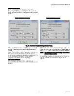
Navigation and Memory Usage

The Honeywell Spyder Tool uses an intuitive, window-based 

interface. A Help button on each screen provides assistance 

with any entry or process.

IMPORTANT

Use the Help button to display context specific help 

for the current window or pane display. See the lower 

left corner of Fig. 6 on page 5 for the location of the 

Help button.

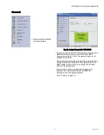
NOTE: At any time, clicking the Preview button (lower left of 

main window, see Fig. 6 on page 5) displays the 

updated wall module LCD as a pop-up. Preview sim-

ulates the actual wall module interface and allows 

you to verify the operation of the current configura-

tion of the wall module. See “Preview” on page 16.
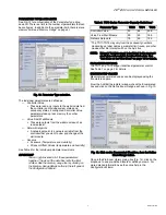
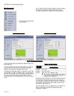
Navigation

Table 3 describes the navigation buttons at the bottom of the 

wall module window. See the bottom of Fig. 7 on page 5 for 

the location of these buttons. Buttons are greyed when 

unavailable.

VAV_Temp_NoBal_NwOvrdTime

VAV_Temp_MnMxBal_NwOvrdTime

VAV_Temp_KfacBal_NwOvrdTime

VAV_Temp_NoBal_AllOverride

SBusWallModule

M27820

RIGHT CLICK

DRAG

AND

DROP

1

2

Table 3. Navigation Buttons.

Item

Function/Use

Help

When clicked, this button provides context sensitive 

help for the currently selected item or parameter.

Preview When clicked, this button displays the updated wall 

module LCD in a pop-up window pane. Preview is 

fully interactive and simulates the actual wall 

module interface as currently configured (see 

“Preview” on page 16 for details).

Save to 

Library

For new custom configurations and standard 

configurations. 

Clicking the button opens the Save to Library 

screen (shown in Fig. 25 on page 17). This action 

allows you to save the entire current wall module 

configuration.

The Save to Library button is disabled until you 

change the configuration (application). After a 

change is made, you can save the new 

configuration into the library under a new name.

Back

Takes you backward one step in the wizard 

interface.

Next

Takes you forward one step in the wizard interface.

Finish 

Clicking this button commits all changes to the 

database, closes the Configuration Wizard, and 

returns you to the wire sheet. 

Cancel

Prompts you with a confirmation message.

If you reply Yes, then all selections/entries made 

since the Save to Library button or Finish button 

was last pressed are ignored, and the wizard 

interface quits.

Содержание Zio TR70

Страница 1: ... three softkeys and two Up Down adjustment keys Models with H also include an onboard humidity sensor PREFACE This Operating Guide is intended to provide configuration information using the Niagara Workbench tool and a general overview of the TR70 Series operator interface Configuration begins with Initial Power Up on page 2 and the general overview begins with Operating the Zio Wall Module on pag...

Страница 2: ...Wall Module LCD screen The new Spyder tool 6 0 or greater assumes the latest Spyder capability At download the Tool reads the brand model of the connected Spyder and determines if it matches the features on the wire sheet If old or new Spyder is programmed with aTR70 it can be physically replaced with a TR71 or TR75 Table 1 TR70 Series Features Features Zio TR70 Zio TR71 ZioPlus TR75 Scheduling x ...

Страница 3: ...ation and Memory Usage The Honeywell Spyder Tool uses an intuitive window based interface A Help button on each screen provides assistance with any entry or process IMPORTANT Use the Help button to display context specific help for the current window or pane display See the lower left corner of Fig 6 on page 5 for the location of the Help button NOTE At any time clicking the Preview button lower l...

Страница 4: ...gories should be below 100 See Fig 4 on page 4 NOTE For a single Zio memory usage must be equal to or less than 100 in order to download the configura tion to the programmable controller If using multiple Zios you should also check the Spyder Resource usage Total Zio memory use is limited to 5K bytes on Spyder View the online help in the WEBs AX Workbench to see troubleshooting tips for reducing m...

Страница 5: ...can use the Remove button to delete unused categories and parameters to free up memory space Fig 7 Category Preview CATEGORY DETAILS When you select a category from the Categories tree list and click the Edit button a details pane displays for that category see Fig 8 on page 6 Here you can enter a category name and description The number of parameters in this category are shown The description tex...

Страница 6: ...rameter from the tree list and click the Edit button a details pane displays for that parameter Here you can select Viewable by Tenant and Editable by Tenant As an example Fig 10 shows the Details for the ROOMTEMP parameter Here you would enter the description select the parameter type from its drop down list enter the decimal accuracy default sensor offset value temperature units and select the d...

Страница 7: ...the data files limits the total number See the memory usage tool by clicking on the Memory Usage Details button in the left pane of the Configuration Wizard The TR71 TR75 may vary from these capacity numbers depending on label names parameter limit reuse and other devices that Zio interacts with on the Sylk bus NOTE Network Variables need to be linked to the appropri ate S Bus wall module s functi...

Страница 8: ... related unoccupied heat setpoint parameter as the low limit and the occupied cooling setpoint parameter as the high limit To assign a setpoint to another setpoint s high or low limit click on the Browse button next to the Low Limit or High Limit field From the Select Parameter dialog box you can select the appropriate setpoint This feature is an alternative to assigning a numeric value in the Hig...

Страница 9: ...ome screen to be the initial Home screen for the wall module after the configuration is downloaded to the wall module The Description text you enter allows more information to be entered on the home screen and will be loaded to the controller but cannot be previewed Use the Option Type selection to choose either single or multiple 1 to 3 parameters to display on the Home screen For the Single Para...

Страница 10: ... Settings button for the Valid States That You Can Override section opens the Override to Occupied Settings dialog box where you can configure values to any desired number from 0 to 255 To conserve Zio memory choose the same Override Type and Timed Override Details for Occupied Unoccupied and Standby Fig 17 Occupancy and Override screens OCCUPANCY STATUS DISPLAY OPTIONS Here you select how the ove...

Страница 11: ...ils will be determined by the programmable controller configuration This option only applies to Occupancy override settings Unoccupied and Standby do not use bypass ADVANCED SETTINGS When the Show Advanced Settings button is clicked overrides to Occupied Unoccupied and Standby options are possible The Override to Unoccupied selection s Settings button displays pop ups similar to the Override to Oc...

Страница 12: ...the fan commend is a network setpoint then the default value is set on the controller s network setpoint The Fan command value cannot be changed from Zio in the Contractor mode After you choose the setting use the Fan Command Preview at the bottom of the window to exercise the Fan softkey to cycle through the options If the Set as Network Setpoint box is checked for the TR71 TR75 the Preview scree...

Страница 13: ...the top of the wall module s LCD screen For TR71 TR75s click on the System Command checkbox to allow the System Command to be configured as a network setpoint The default System Command option is Off Heat Heat Only The System commands are selectable The System command value cannot be changed from Zio in the Contractor mode After you choose the setting use the Preview button at the bottom of the wi...

Страница 14: ... or not the tenant can view or edit etc We recommend setting the time in Spyder before configuring the Schedule Time in the configuration tool NOTE Setting an invalid time at Zio will cause Spyder to set the time to invalid You also have the ability to configure how the Spyder schedule will display at the TR75 8 day schedule 7 day schedule 5 2 1 day schedule or the 5 2 schedule If using the 5 2 1 ...

Страница 15: ...tem changes from the TR71 TR75 The password option is not available for the TR70 The password can be assigned an eight character label that is displayed at the TR71 TR75 and a four digit password from 0000 to 9999 All TR71 TR75s on a Spyder can have the same or unique passwords If the password option is enabled and the password is forgotten it can be retrieved through the WEBs AX Workbench in the ...

Страница 16: ...ey rectangles below the labels of the preview display exercises the features you have configured NOTE Since the up and down arrow keys do not display in Preview mode no adjustments to parameters e g setpoint temperature can be made Fig 24 shows your current configuration of the wall module Home screen You can select either the Tenant or Contractor view The three softkeys in the preview LCD display...

Страница 17: ...o see how the wall module LCD screen will operate for your selected configuration see Preview on page 16 Confirm Memory Usage is within Limits To view the current memory use information click on the Memory Usage Details button A new window opens and displays a a bar graph indicating the percentage of current memory used in each memory category Each of the memory categories should be below 100 You ...

Страница 18: ...see an example in Fig 26 A maximum of four Zios may be wired on a single Sylk bus with no more than one TR70 per bus When making links from existing blocks to the wall module function block input slots there is no need to break the existing links from these existing blocks The new tool allows for multiple output connections When connecting to slots on function blocks which lie on different wire sh...

Страница 19: ...gate from one digit to the next Fig 28 Password entry screen Contractor Mode Operation Contractor mode allows advanced options such as modifying configured parameters using the softkeys Contractor mode also allows for customizing the tenant s view including setting the tenant s Home screen and controlling the tenant s View More access which can provide the tenant with a view of the configured para...

Страница 20: ...ey moves to the next parameter Click the DONE softkey when finished The CANCEL softkey exits VIEW MORE without saving changes to that parameter Fig 31 Set View More parameter display PARAMETERS allows the contractor to monitor and or adjust parameters in the programmable controller Clicking the PARAMETERS softkey displays the first configured category as shown in Fig 31 and the softkeys change to ...

Страница 21: ... Schedule option lets you modify the schedule and change Spyder s time The desired scheduling option 8 day 7 day etc is setup in the Configuration Wizard see Wall Module Configuration on page 4 and based on that selection option screens vary The example below shows the flow for viewing editing a schedule Use the Edit softkey to move to the next screen and use the up down arrows to change values Wh...

Страница 22: ... softkey does not display on the tenant s Home screen 3 If there are no parameters configured for tenant access the VIEW MORE softkey does not display on the tenant s Home screen FAN allows the tenant to adjust the fan settings depending on the fan options 2 3 or 5 position configured As shown in Fig 41 each click of the FAN softkey changes the fan icon display between 2 position ON and AUTO 3 pos...

Страница 23: ...finished Fig 43 System and View More display for Tenant Tenant Home Screen Display The LCD display may be customized for the tenant This section includes a few examples of the various tenant Home screens that are configurable for the LCD Wall Modules Not all possible Home screens are illustrated here There are many other configurable Home screens NOTE Home screens can display one to three of any o...

Страница 24: ... Home screen with Room Temperature and Time predominant NOTE In Fig 47 there are no Fan System or View More softkey options configured for this Home screen Fig 48 Sample Tenant Home screen with a single custom parameter NOTE In Fig 48 the Home screen is configured with only a single custom parameter See Preview on page 9 Fig 49 View More display showing CO2 sensor value from controller NOTE As sho...

Отзывы: