background image

Behavior of the target values

during day and reduced mode

B C

B

Day mode setpoint

Reduced mode
setpoint

///

C

(

)

Содержание ZG 215VN

Страница 1: ...OPERATION AND PUTTING INTO SERVICE Comfort Compact Controller ZG 215VN P1 C B auto1 ZG215VN 8 0 8311 7151 CB50268 P1 C B 1 4 2 3 7 6 C B L1 L2 P1 A S 5 B C B C ...

Страница 2: ...t discharge temperature control FT ZG 215VN CB2282 TW VM V DR LF ZG Control Unit VM Servomotor DR Heating mixing valve LF Air flow sensor TW Temperature selector opt FT Frost protection thermostat V Air heater ...

Страница 3: ...perature control for a floor heating system P VF T ZG215VN TW ZR VM CBZG107 cdr ZG Control Unit VM Servo motor ZR Heating mixing valve VF Flow sensor TW Temperature selector T Temperature limiter P Heating circuit pump ...

Страница 4: ...va lue the controller commands the VM servo motor to adjust the ZR DRmixing valve The mixing valve performs the necessary change to the mixing ra tio between the heated supply water and the heating circuit s retur ning cooled water TheTW temperature selector is used as remote control By means of the P2 selector knob the flow or supply temperature can be mo dified The temperature selector is not ab...

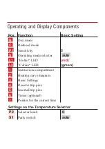
Страница 5: ... S Operating mode selector auto L1 Hotter LED red L2 Colder LED green 1 Instructions compartment 2 Heating curve diagram 3 Basic Settings 4 Reserve trip pins 5 Inserted trip pins 6 Timer optional 7 Pointer for the current time Settings on the Temperature Selector P2 Selector knob 0 S1 Party switch auto ...

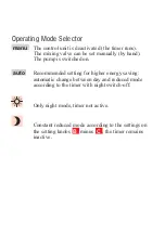
Страница 6: ...y by hand The pump is switched on auto Recommended setting for higher energy saving automatic change between day and reduced mode according to the timer with night switch off Only night mode timer not active Constant reduced mode according to the settings on the setting knobs B minus C the timer remains inactive ...

Страница 7: ...ED s light up neutral mixing valve stops only red LED lights up hotter mixing valve opens only green LED lights up colder mixing valve closes In the manu settings of the operating mode selector S there is no LED display ...

Страница 8: ...remaining basic factory settings are printed under 3 on the control unit Timer for reduced mode 6 With the aid of the timer the room temperature during idle periods can be reduced automatically to save on operating costs The timer has a built in power reserve of approx 60 hours thanks to a rechargeable battery ...

Страница 9: ...roomsareheatedwellinthemorning the heating system s day mode should be activated between a half an hour and an hour before using the rooms Energy saving tip Reduced mode can be activated up to an hour before the room is left The storage capaci ty of the heating system and building is enough to keep the rooms warm for some time Timer with day program The day program is repeated every 24 hours If a ...

Страница 10: ... temperature blue pin 22 00 h Start night decrease Timer with week program The timer has a changeable dial With the week program dialling a different heating program for each weekday is possible The dial is prepared ex factory for the day program and if required itcanbechangedtoweekprogram seeinstallationinstructions Setting the right time To set the time the time dial is to be placed on the trip ...

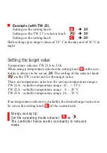
Страница 11: ...he desired target value for day mode If a temperature selector is used as a remote control the setting knob B is to be set on 20 Reduced mode setting knob C By means of setting knob C the intensity of the decrease to be ac tivated with the timer can be set The setting range varies from 0 to 100 K C The decrease set with setting knob C refers to the temperature either on setting knob B or on the TW...

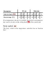
Страница 12: ...on troller is always to be set on 20 The setting of the selector knob P2 on the TW is relevant for the target value There are temperature selectors for various temperature ranges TW 21A settable temperature range 15 15 C TW 22A settable temperature range 0 30 C TW 23A settable temperature range 20 70 C If no temperature selector is available the desired target value is to be set on the setting kno...

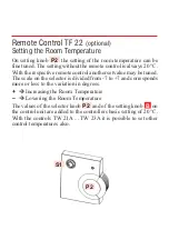
Страница 13: ...nother setvalue may be tuned The scale on the selector is divided from 7 to 7 and corresponds more or less to the variation in degrees è Increasing the Room Temperature è Lowering the Room Temperature The values of the selector knob P2 and of the setting knob B on the control unit are added to the controllers basic setting of 20 C With the controls TW 21A TW 23A it is possible to set other control...

Страница 14: ... 22 23 Room temp C 19 20 21 22 20 21 22 23 If no temperature selector is available the desired room tempera ture can be set only on the setting knob B of the control unit Party switch S1 The party switch at the temperature controller has no function here ...

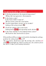
Страница 15: ...e selector knob P2 n Check the setting of the control unit Setting knobs B C and operating mode selector S n Is the timer running Is the displayed time correct èCheck the time and switch on point If the problem still has not been solved after checking the settings position the setting knob B on 7 The servomotor should now open the mixing valve and the red LED L2 should light up If this is not the ...

Страница 16: ...Manual mode CB5043 7 cdr ...

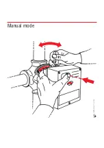
Страница 17: ...atures are reached The coupling incorporated in the mixing valve drive unit provides for the release of the connection between the motor and the mixing valve Press firmly on the unlock key on the cover of the drive unit and keep the key pressed firmly Use the setting lever to set the mixing valve in the desired position After eliminating the problem the mixing valve is set again to the right posit...

Страница 18: ...Behavior of the target values during day and reduced mode B C B Day mode setpoint Reduced mode setpoint C ...

Страница 19: ...to the left until the connector is released n 3 Remove the timer To install the timer proceed in the opposite order Regulation Stability Sensitivity The stability of the regulation can be modified with the setting potentiometer P1 For the regulation technician Bymeansof P1 settheproportionalrangeofthePDcontrolunit Recommended basic setting P1 è 10 In case of unstable regulation set higher values ...

Страница 20: ...VF 20A VF20 LF20 Flow and airflow sensors ...

Страница 21: ...Compact Control Units ZG 215N 215VN 252N EN1H 0181 GE51 Operating Instructions ZG 252N EN2H 0215 GE51 ZG 215N EN2H 0216 GE51 ZG 215VN EN2H 0217 GE51 Informationsschrift Planning broschure in German L3 Komfort Compact Regler GE0H 0327 GE51 ...

Страница 22: ...gstechnik http www honeywell de hga Honeywell AG Böblinger Straße 17 D 71101 Schönaich Telefon 49 70 31 637 01 Telefax 49 70 31 637 493 Technical data may be changed without prior notice EN2H 0217 GE51 R0702 7157 560 ...

Отзывы: