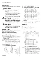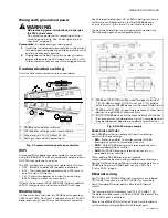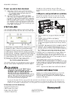
QUICK START INSTALLATION GUIDE
31-00091-02
WEB-8000 Controller
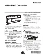
Fig. 1. WEB-8000 controller (with one option module).
This is a quick-start document for the mounting and
wiring of the following products.
NOTE:
WEBs-N4.1 software is required for any
WEB-8000 controller. A maximum of four (4) total
option modules are supported. Separate limits
may exist in the controller’s license, which can
further limit options.
See the controller’s full
Mounting and Wiring Guide
for
complete hardware installation details.
Included in this package
Included in this package you should find the following
items:
• WEB-8000 controller.
• MicroSD card in plastic case. See “Preparation,” page 1.
• Coax-mount, dual 2.4/5.8GHz antenna for WiFi, two 3-
position RS485 connector plugs, and a grounding wire.
• This WEB-8000
Controller Quick Start Install Sheet
.
Material and tools required
• One of the following:
—
UL listed, Class 2, 24Vac transformer, rated at min-
imum of 24Va. A dedicated transformer is required
(cannot power additional equipment),
or
—
24Vdc power supply, capable of supplying at least
1A (24W),
or
—
WPM-8000 wall-mount AC power adapter with bar-
rel connector plug.
• DIN rail, type NS35/7.5 (35mm x 7.5mm) and DIN rail
end-clips (stop clips), recommended for any
installation that includes option modules.
• Suitable tools and fasteners for mounting the unit and
any accessories.
Preparation
Before mounting a new controller, you must insert the
included microSD flash memory card. Note the card has
the unique Niagara identity (host ID) for the unit, set at the
factory.
CAUTION
Disconnect all power to the controller before
removing or inserting the microSD card.
Otherwise, equipment damage is likely to occur.
Fig. 2. MicroSD card location in controller.
NOTE:
Data on the microSD card is encrypted by a spe-
cial “system password” stored in the controller
base. If swapping in a card from a previously con-
figured unit, you must re-enter this same pass-
word, using a serial connection to the unit’s
Debug port.
Model
Description
WEB-8000
DIN-mount, 24Vac/dc powered, Niagara
4® area controller. See the product data
sheet for complete specifications.
WPM-8000 Wall-mount, Class 2 universal AC power
adapter supplying 24Vdc.
M35795A
1
Access shutter for microSD card (slide to open or close).
2
Card carrier inside controller.
3
MicroSD card to insert or remove from card carrier.
Insert card label-side up, until spring catch latches. If
properly inserted, the card is behind the shutter track.
M35796A
1
3
2


