


Sensor-Controller Systems
70-6925
135
H
u
m
idi
st
at
s
an
d
Th
er
m
o
st
at
s
Controller
s
Sensors
Relay
s
Switch
es
Actuators
Va
lv
e
s
Ac
ces
sor
ie
s
En
gi
ne
eri
ng
Gu
ide
Cr
o
s
s
Refere
nc
e
The humidistat can be used in a one-pipe or two-pipe
configuration and is available as either a bleed-type humidistat
or a two-pipe capacity humidistat using a capacity amplifier. The
humidistat may be direct or reverse acting. The high-capacity
humidistat has a capacity amplifier.
Pressure Controllers
Pressure controllers can be divided into two classes according
to the pressure range of the measured variable. High-pressure
controllers measure and control high pressures or vacuums
measured in pounds per square inch or in inches of mercury
(e.g., steam or water pressures in an air conditioning system).
Low-pressure controllers measure and control low pressures
and vacuums measured in inches of water (e.g., pressure in an
air duct).
High- and low-pressure controllers have different size
diaphragms. In both types, one side of the diaphragm is
connected to the pressure to be controlled, and the other side is
connected to a reference pressure. Pressures can be
measured in respect to atmospheric pressure or another
pressure source. The low-pressure controller is available in
both bleed-type and pilot-bleed designs.
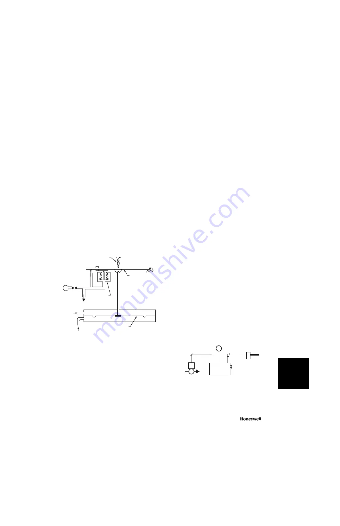
Figure 20 shows a schematic of a bleed-type, low-pressure
controller. The direct-acting pressure sensor measures static
pressure from a pressure pickup located in a duct. A reference
pressure, from a pickup located outside the duct, is applied to
the other side of the diaphragm.
Fig. 20. Bleed-Type Static Pressure Controller.
On an increase in static pressure, the increased force on the
diaphragm exceeds the force of the setpoint spring, pulling the
main lever downward. A setpoint adjustment screw determines
the tension of the setpoint spring. As the main lever is pulled
downward, it moves closer to the nozzle, restricts the airflow
through the nozzle, and increases the pressure in the branch.
The action continues until the pressure on the feedback bellows
balances the static pressure on the diaphragm.
On a decrease in static pressure, or if the static pressure sensor
is piped for reverse action (high- and low-pressure pickups
reversed), the diaphragm moves upward to move the main
lever away from the nozzle and reduce the pressure in the
branch.
For differential pressure sensing, the two pressure pickup lines
connect to opposite sides of the pressure sensor diaphragm.
SENSOR-CONTROLLER SYSTEMS
A sensor-controller system is made up of a pneumatic
controller, remote pneumatic sensors, and a final control
element. The controller provides proportional or proportional
integral control of temperature, humidity, dew point, or pressure
in HVAC systems. Sensors do not have a setpoint adjustment
and provide a linear 3 to 15 psi signal to the controller over a
fixed sensor range. The controller compares the sensor input
signal with the setpoint signal. The difference is the pilot input to
a signal amplifier, which provides a branchline pressure to the
controlled device. Thus the controller acts as a general purpose
pneumatic amplifier.
Pneumatic Controllers
Controllers generally use diaphragm logic, which allows flexible
system application, provides more accurate control, and
simplifies setup and adjustment for the needs of each system.
Controllers may be proportional only or proportional-integral
(PI). The integral function is also called “automatic reset”.
Proportional and PI controllers are available with single sensor
input or dual-sensor input for resetting the primary sensor
setpoint from a second sensor. They are also available with
integral or remote setpoint adjustment.
The single-input controller consists of a signal amplifier feeding
a capacity amplifier. The capacity amplifier is discussed under
PILOT BLEED SYSTEM. A dual-input controller has inputs from
a primary temperature sensor and a reset temperature sensor.
The reset sensor resets controller setpoint. Reset can be
negative or positive.
Figure 21 depicts a single-input controller as it would appear in
a simple application. Figure 22 depicts a dual-input controller
with manual remote setpoint control. In Figures 21 and 22 the
sensors are fed restricted main air from the controllers. Where
sensors are located extremely remote from the controller, a
remote restrictor may be required.
Fig. 21. Single-Input Controller.
PRESSURE SENSOR
REFERENCE
PRESSURE
STATIC
PRESSURE
C2609
SETPOINT
SPRING
DIAPHRAGM
M
BRANCH
FEEDBACK
BELLOWS
MAIN LEVER
M
SINGLE INPUT
CONTROLLER
HOT WATER
VALVE
MAIN AIR
(18 PSI)
TEMPERATURE
SENSOR
M10293
Содержание VP525C
Страница 58: ...50 customer honeywell com 70 6925 ...
Страница 120: ...112 customer honeywell com 70 6925 ...
Страница 166: ...158 customer honeywell com 70 6925 ...