


Installation Instruction VARIODYN
®
D1 System
66
FB 798663.GB0 / 05.19
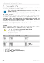
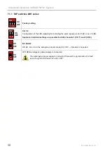
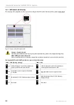
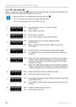
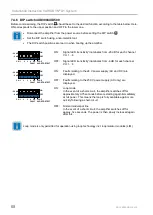
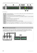
7.4.4 DIP switch 4XD250B
Before commissioning, the DIP switch
9
should be set to the desired function according to the table below. Here,
OFF corresponds to the upper position and ON to the lower one.
•
Always power-down the Amplifier before setting the DIP switch
9
.
•
Use a non-metallic tool to change the settings of the DIP switch.
•
The DIP switch settings are read on Amplifier power-up.
1
ON
1
8
2 3 4 5 6 7
OFF:
Standard operation of the 4 x 125 watt final stages
(factory setting)
ON:
Switch setting not permitted
2
ON
1
8
2 3 4 5 6 7
OFF:
All channels will be auto-enabled if no external control signals are
provided. Individual control of amplifier channels.
ON:
All channels will be disabled if no external control signals are provided.
Control of amplifier channels in pairs. (factory setting).
3
ON
1
8
2 3 4 5 6 7
OFF:
Charging function for the connected batteries activated
(factory setting).
ON:
Battery charging function deactivated. Supply via an external
power supply.
4
ON
1
8
2 3 4 5 6 7
OFF:
Monitoring of the connected batteries activated (factory setting).
ON:
No monitoring of the connected batteries (required if no batteries are
connected).
5
ON
1
8
2 3 4 5 6 7
OFF:
Display of the audio signal strength via the two green LED <High/Low
channel> on the front side of the amplifier in the range -20 dB (low)
and -6 dB (high). Display function for the deviation from the nominal
value (factory setting).
ON:
Display of the audio signal strength via the two green LED <High/Low
channel> on the front side of the amplifier in the range -6 dB (low) and
-3 dB (high). Display function for the deviation from the nominal value.
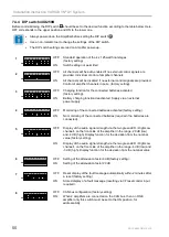
6
ON
1
8
2 3 4 5 6 7
OFF:
Setting of the attenuation factor 6 dB (factory setting).
ON:
Setting of the attenuation factor 20 dB.
7
ON
1
8
2 3 4 5 6 7
OFF:
Reset display of the fault message automatically within 2 minutes after
a reset (factory setting).
ON:
Stored display of a fault message (resetting via I/F reset control input
required).
8
ON
1
8
2 3 4 5 6 7
OFF:
CAN bus configuration (factory setting)
ON:
When 2 amplifiers are connected on the CAN bus, then on ONE
amplifier only this switch must be set to the ON position, for
addressability.


