


Installation Instruction VARIODYN
®
D1 System
26
FB 798663.GB0 / 05.19
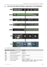
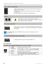
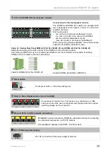
110 … 230 V AC – Rated voltage
A power supply cable is included in the delivery. Observe local standards and
guidelines prior to operation.
Alternatively, the connection can take place via the main switch unit (MSU).
See chapter 6.3.
Exception: DOM (Part No. 583361.22.UL and 583362.22.UL)
Fuses
1,6AT 5AT
F1
F2
Device fuses F1 = 1.6 AT / 250 V and F2 = 5 AT / 250 V
Never repair or bridge the device fuse that is installed or replace it
with anything other than the stated type!
Two Wire Interface (TWI)
TWI
Connection option for a time synchronisation module (TCM),a Contact-Interface-
Module (CIM), a service PC, or an fire alarm control panel. Do not connect
second jack!
A TWI-RS232 adapter (Part No. 583386.21) is also required for connecting the service PC
and the FACP.
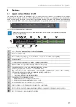
PA CH1/2 and PA CH3/4 (output to power amplifier)
PA CH 1/2
PA CH 3/4
0 dB signal output for connection to a power amplifier (PA).
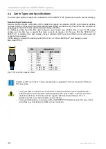
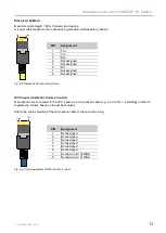
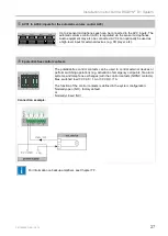
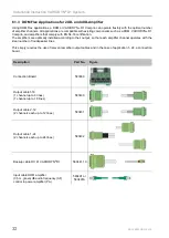
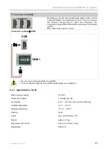
Power amplifier (PA)
Connection
PIN
Assignment of RJ45 socket for connection to a DOM
D1 LINK
CONTROL
INTERFACE
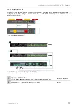
1
CH2 IN+
Systematic input for channel 2 (CH2)
2
CH2 IN-
3
System Error
Normal operation: + 24 V (12 V … 24 V), Aux (battery) supply
error 0 V, mains (110 …230 V) supply error 24 V intermittent
4
CH1 IN+
Systematic input for channel 1 (CH1)
5
CH1 IN-
6
0 V
0 V reference potential for the connection to VARIODYN
®
D1
7
Ext. 24 V
Ext. 24 V active
'Ext. amp enable' PIN monitored
8
Ext. amp. enable
Switch off channel 1 (CH1) and channel 2 (CH2)
High level
(12 V … 28 V)


