background image

1

69-0329—4

V8205, VR8205 Direct Ignition

Combination Gas Controls

Installation Instructions for the Trained Service Technician.

G. S.  •  Rev. 12-93  •  ©Honeywell Inc. 1993  •  Form Number 69-0329—4

TABLE 1—DIRECT IGNITION COMBINATION GAS CONTROL MODELS.

TABLE 2—MODEL NUMBER

SUFFIX LETTER DESIGNATION.

TABLE 3—FLANGE PART NUMBERS.

NOTE: Flange Kits include one flange with attached O-ring

and four mounting screws. TRADELINE

®

 kits include a

9/64 in. hex wrench, as noted.

APPROVALS:

American Gas Association design certificate: L2025006.
Canadian Gas Association design certificate: L2025006.
Australian Gas Association design certificate: 4214.
Approved for Delta C applications.

Installation

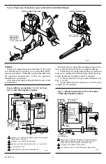
WHEN INSTALLING THIS PRODUCT…

1. Read these instructions carefully. Failure to follow

them could damage the product or cause a hazardous condi-
tion.

2. Check the ratings given in the instructions and on the

product to make sure the product is suitable for your appli-
cation.

3. Installer must be a trained, experienced service tech-

nician.

4. After installation is complete, check out product op-

eration as provided in these instructions.

Part No.

Inlet/Outlet

Pipe Size

Flange

Type

Less Hex

Wrench

With Hex

Wrench

3/8 in. NPT

Straight

393690-1

393690-11

Elbow

393690-2

393690-12

1/2 in. NPT

Straight

393690-6

393690-16

Elbow

393690-3

393690-13

3/4 in. NPT

Straight

393690-4

393690-14

Elbow

393690-5

393690-15

Model No.

Suffix

Letter

Ambient

Temperature

Range

Regulator

Type

A

0° F to 175° F

Standard

[-18° C to 79° C]

C

Step-opening

H

Slow-opening

K

-40° F to 175° F

[-40° C to 79° C]

M

Standard

P

Step-opening

Model

Voltage/

Frequency

Number of  

Automatic Operators

Gas Control  

Knob Positions

Current Draw

V8205

24V/60 Hz

One

OFF-ON

0.30A

VR8205

24V/60 Hz

Two

OFF-ON

0.5A

These direct ignition gas controls are used in gas-fired

appliances with up to 200 cfh capacity on natural gas. They
include safety shutoff, a manual valve, one or two auto-
matic operators and a pilot adjustment. See Table 1 for
model differences and Table 2 for temperature ranges and
regulator types.

BODY  PATTERN:  Straight  through  with  1/2  in.  inlet

and 1/2 in. outlet.

PIPE ADAPTERS: Angle and straight adapters available

for 3/8, 1/2 and 3/4 in. pipe. See Table 3.

These gas controls are factory-set for natural (and manu-

factured) gas or LP gas. Do not attempt to use a control set
for natural (manufactured) gas on LP gas, or a control set
for LP on natural (manufactured) gas.

Controls with standard or slow opening regulators can be

converted from one gas to the other with a conversion kit
(ordered separately). Order part no. 393691 to convert from
natural (manufactured) to LP gas; order part no. 394588 to
convert from LP to natural (manufactured) gas. Controls
with step opening regulators cannot be converted.

Application

Содержание V8205

Страница 1: ...0 6 393690 16 Elbow 393690 3 393690 13 3 4 in NPT Straight 393690 4 393690 14 Elbow 393690 5 393690 15 Model No Suffix Letter Ambient Temperature Range Regulator Type A 0 F to 175 F Standard 18 C to 79 C C Step opening H Slow opening K 40 F to 175 F 40 C to 79 C M Standard P Step opening Model Voltage Frequency Number of Automatic Operators Gas Control Knob Positions Current Draw V8205 24V 60 Hz O...

Страница 2: ... controls are factory set for natural and manufactured or LP gas Do not attempt to use a control set for natural manufactured gas on LP gas or a control set for LP on natural manufac tured gas Gas controls with standard or slow opening regulators can be converted from one gas to the other with a conver sion kit ordered separately Order part no 393691 to convert from natural manufactured to LP gas ...

Страница 3: ...y direction from the upright position of the gas control knob including vertically 2 Mount the control so gas flow is in the direction of the arrow on the bottom of the control 3 Thread pipe into control Do not thread pipe to far Valve distortion or malfunction may result if the pipe is inserted too deeply refer to Table 4 TABLE 4 NPT PIPE THREAD LENGTH IN in OUTLET PRESSURE TAP INLET OUTLET WIRIN...

Страница 4: ...age 1 Check the power supply rating on the gas control and make sure it matches the available supply Install the trans former thermostat and other controls as required 2 Connect control circuit to gas control terminals See Figs 4 6 and 7 3 Adjust thermostat heat anticipator to 0 50A rating stamped on valve operator Fig 7 Wiring connections for 24 volt control in S89 direct ignition system WHITE BL...

Страница 5: ...operly adjusted for complete combustion Followinstructionsofappliancemanufacturer 2 IF CHECKING GAS INPUT BY CLOCK ING GAS METER Make certain there is no gas flow through the meter other than to the appliancebeingchecked Otherappliancesmust remain off with their pilots extinguished or their consumption must be deducted from the meter reading Convert flow rate to Btuh as described in Gas Controls H...

Страница 6: ...htoff characteristics TABLE 5A PRESSURE REGULATOR SPECIFICATION PRESSURES IN kPa CHECK SAFETY LOCKOUT SLOW OPENING CONTROLS ONLY 1 With the system power off and the thermostat set to call for heat manually shut off the gas supply 2 Energize ignitor control and start timing safety lock out time When spark ignition terminates stop timing When using the VR8205H step opening control the specified igni...

Страница 7: ...PERSONAL INJURY OR LOSS OF LIFE 1 Before lighting smell around the appliance area for gas If the appliance uses LP bottled gas be sure to smell next to the floor because LP gas is heavier than air If you smell gas immediately shut off the manual valve in the gas piping to the appliance or on LP at the tank Do not try to light any appliance Do not touch any electrical switch or use the phone Leave ...

Страница 8: ... LP installation immediately shut off the manual valve in the gas piping to the appliance or on LP at the tank Don t touch any electrical switch or use the phone Leave the building and call your gas supplier If your gas supplier cannot be reached call the fire department Failure to do so may result in fire or explosion 6 If you don t smell gas turn knob on gas control counterclockwise to ON 7 Repl...

Отзывы: