


INSTALLATION INSTRUCTIONS
62-0255-05
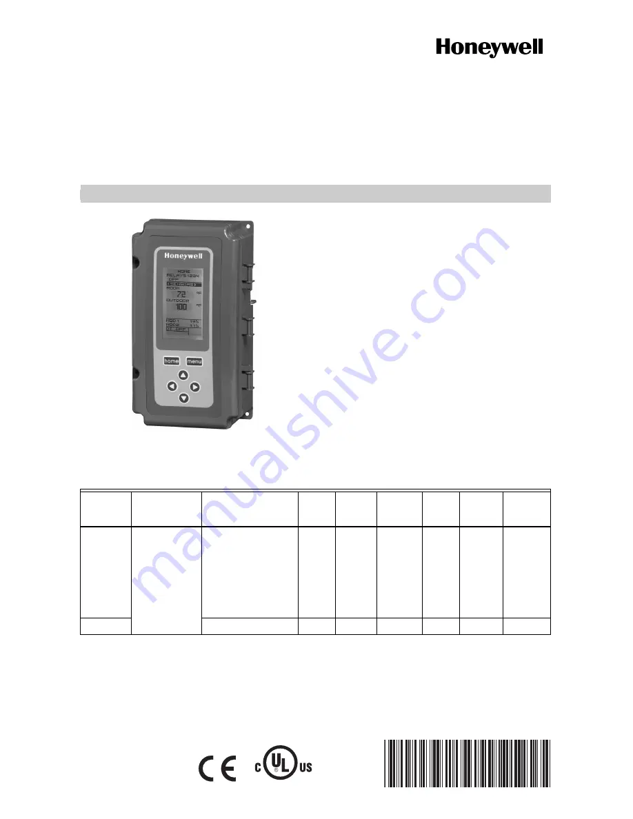
E4436
T775U Series 2000 Electronic
Stand-Alone Controller
PRODUCT DESCRIPTION
The T775 electronic stand-alone controllers are the next
generation of universal controls capable of remote
sensing of temperature, humidity, pressure, etc. and
providing switched and proportional outputs to various
types of loads. A built-in time clock is standard.
The T775U controller allows a wide range of sensors to
be configured. Humidity, pressure, temperature, or any
0-5 Vdc, 0-10 Vdc, or 4-20 mA input is supported.
A Reset function is available where the Sensor B
temperature (e.g. outside temperature) is used to provide
reset control for Sensor A (e.g. humidity). For example,
as the outside temperature gets colder, the setpoint can
automatically be adjusted to prevent condensation.
IMPORTANT
The T775U is an operating control, not a limit or
safety control. If used in applications requiring
safety or limit controls, a separate safety or limit
control device is required.
Table 1. T775U Controller Configurations.
Controller
Model
a
a
The T775U includes a digital input for use with the disable or setback option.
Description
Replaces
Output
Reset
SPDT
Relay
Outputs
Analog
(Mod)
Outputs
b
b
The modulating (analog) outputs may be 4-20 mA, 0-10 Vdc, 2-10 Vdc, or Series 90 selectable.
Sensor
Inputs
Nbr of
Sensors
Included Enclosure
T775U2006
Universal:
Humidity,
Pressure,
Temperature,
etc.
H775A1006
H775A1022
H775A1048
H775A1063
H775B1005
H775C1004
c
H775D1003
c
H775E1002
c
c
For the H775C1004, H775D1003, and H775E1002 model replacement, the T775U only partially replaces the function
of these devices. Check application for suitability.
Yes
2
2
2
d
d
For the sensor inputs, Sensor A can be 0-10Vdc, 4-20mA, or a standard temperature input. Sensor B is a standard
temperature sensor input only. Sensor B is used only for reset on the T775U2001.
None
NEMA 1
T775U2016
N/A
Yes
2
2
2
e
e
The T775U2016 can control Sensor A (universal) and Sensor B (temperature) independently, like other standard
T775 controllers.
None
NEMA 1
Содержание T775U2006
Страница 39: ...T775U SERIES 2000 CONTROLLER 39 62 0255 05 ...


