background image

SPYDER® LON PROGRAMMABLE, VAV/UNITARY CONTROLLERS

63-2685—03

8

The application engineer must review the control job 

requirements. This includes the sequences of operation for the 

controller, and for the system as a whole. Usually, there are 

variables that must be passed between the controller and other 

Spyder Lon controller(s) that are required for optimum system-

wide operation. Typical examples are the TOD, Occ/Unocc 

signal, the outdoor air temperature, the demand limit control 

signal, and the smoke control mode signal. 

It is important to understand these interrelationships early in 

the job engineering process, to ensure proper implementation 

when configuring the controllers. Refer to the controller 

Application Guides. 

Power Budget

A power budget must be calculated for each device to 

determine the required transformer size for proper operation. A 

power budget is simply the summing of the maximum power 

draw ratings (in VA) of all the devices to be controlled. This 

includes the controller itself and any devices powered from the 

controller, such as equipment actuators (ML6161 or other 

motors) and various contactors and transducers. 

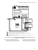
IMPORTANT

• If a controller is used on Heating and Cooling Equip-

ment (UL 1995, U.S. only) and transformer primary 

power is more than 150 volts, connect the transformer 

secondary common to earth ground (see Fig. 12 on 

page 10).

• When multiple controllers operate from a single 

transformer, connect the same side of the transformer 

secondary to the same power input terminal in each 

device. The earth ground terminal (terminal 3) must 

be connected to a verified earth ground for each 

controller in the group (see Fig. 13 on page 11).

POWER BUDGET CALCULATION EXAMPLE

Table 3 is an example of a power budget calculation for  typical 

PVL0000AS, PVL4022AS, and PVL6436AS controllers. While 

the example is shown for only these models, the process is 

applicable for all controller models.

Table 3. Power budget calculation example.

The system example above requires 30.7 VA of peak power. 

Therefore, a 100 VA AT92A transformer could be used to 

power one controller of this type. Because the total peak power 

is less than 33 VA, this same transformer could be used to 

power three of these controllers and meet NEC Class 2 

restrictions (no greater than 100 VA). 

See Fig. 11–Fig. 13 beginning on page 10 for illustrations of 

controller power wiring. See Table 4 for VA ratings of various 

devices.

Table 4. VA ratings for transformer sizing.

For contactors and similar devices, the in-rush power ratings 

should be used as the worst case values when performing 

power budget calculations. Also, the application engineer must 

consider the possible combinations of simultaneously 

energized outputs and calculate the VA ratings accordingly. 

The worst case, which uses the largest possible VA load, 

should be determined when sizing the transformer. 

Each controller requires 24 Vac power from an energy-limited 

Class II power source. To conform to Class II restrictions (U.S. 

only), transformers must not be larger than 100 VA. A single 

transformer can power more than one controller.

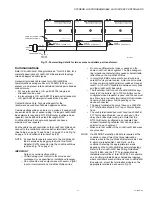
GUIDELINES FOR POWER WIRING ARE AS FOLLOWS:

— For multiple controllers operating from a single 

transformer, the same side of the transformer 

secondary must be connected to the same power input 

terminal in each device. The earth ground terminal 

must be connected to a verified earth ground for each 

controller in the group (see Fig. 13 on page 11). 

Controller configurations are not necessarily limited to 

three devices, but the total power draw, including 

accessories, cannot exceed 100 VA when powered by 

the same transformer (U.S. only).

— See Fig. 12 on page 10 for controller power wiring used 

in UL 1995 equipment (U.S. only).

— Many controllers require all loads to be powered by the 

same transformer that powers the controller.

— Keep the earth ground connection wire run as short as 

possible (refer to Fig. 11–Fig. 13 beginning on 

page 10).

— Do not connect earth ground to the controller’s digital 

or analog ground terminals (refer to Fig. 11 and Fig. 

13).

Device

VA

Information

Obtained From

PVL0000AS, 

PVL4022AS, and 

PVL6436AS 

controllers (include 

Series 60 Floating 

Damper Actuator)

9.0

See “Specifications” on 

page 3.

R8242A Contactor 

fan rating

21.0

TRADELINE

®

 Catalog 

inrush rating

D/X Stages

0.0

For example, assume 

cooling stage outputs are 

wired into a compressor 

control circuit and have no 

impact on the budget.

M6410A Steam 

Heating Coil Valve

0.7

TRADELINE

®

 Catalog, 

0.32A 24 Vac

TOTAL

30.7

Device

Description

VA

PVL0000AS, 

PVL4022AS, and 

PVL6436AS 

controllers and 

Series 60 Floating 

Damper Actuator

Controller and Actuator

9.0

PUL1012S, 

PUL4024S, 

PUL6438S,  

PVL4024NS, or   

PVL6438NS

Controller

5.0

ML684

Versadrive Valve Actuator

12.0

ML6161

Damper Actuator, 35 lb-in.

2.2

ML6185

Damper Actuator SR 50 lb-in

12.0

ML6464

Damper Actuator, 66 lb-in.

3.0

ML6474

Damper Actuator, 132 lb-in.

3.0

R6410A

Valve Actuator

0.7

R8242A

Contactor

21.0

Содержание Spyder PUL1012S

Страница 1: ...identical in design and capability in every detail except for the licensing The Individual Licensing of the Spyder ILCs The License is built in allows them to be programmed and downloaded with any brand of the Niagara Workbench or JACE controller The Spyder ILCs are identified with a suffix on the Part Number of ILC Example PUL6438S ILC follows all the same Installation Instructions information as...

Страница 2: ...d Service Offices in all principal cities of the world Manufacturing in Australia Canada Finland France Germany Japan Mexico Netherlands Spain Taiwan United Kingdom U S A Table 1 Controller configurations a One Universal Input UI 1 is user selectable as a fast digital pulse meter Each controller communicates via the 78 kbps Echelon LONWORKS Network using the FTT 10A LONWORKS interface and is LONMA...

Страница 3: ...n circuit False Closed circuit True Resistance Open circuit 3 000 Ohms Closed circuit 500 Ohms Digital Triac Output DO Circuits Voltage Rating 20 to 30 Vac 50 60Hz Current Rating 25 mA to 500 mA continuous and 800 mA AC rms for 60 milliseconds Analog Output AO Circuits Analog outputs can be individually configured for current or voltage ANALOG CURRENT OUTPUTS Current Output Range 4 0 to 20 0 mA Ou...

Страница 4: ...pped hard wired to the controller The actuator mounts directly onto the VAV box damper shaft and has up to 44 lb in 5 Nm torque 90 degree stroke and 90 second timing at 60 Hz The actuator is suitable for mounting onto a 3 8 to 1 2 in 10 to 13 mm square or round VAV box damper shaft The minimum VAV box damper shaft length is 1 9 16 in 40 mm The two mechanical end limit set screws control the amount...

Страница 5: ...the angle of the damper open to closed is 90 degrees a Manually open the damper fully rotate counterclock wise b Using the Declutch button rotate the universal shaft adapter fully counterclockwise c Mount the actuator to the damper box and shaft d Tighten the two bolts on the centering clamp 8 mm wrench 70 8 88 5 lb in 8 10 Nm torque When the actuator closes the damper rotates CW 90 degrees to ful...

Страница 6: ... 2 2 2 2 2 2 2 2 3 3 1 2 3 4 5 6 7 8 0 9 3 3 3 3 3 3 3 3 4 5 3 4 146 10 5 16 262 NOTE CONTROLLER CAN BE MOUNTED IN ANY ORIENTATION PANEL MOUNTING HOLE 4X 3 16 IN 4 5 M28647 5 3 64 128 8 5 16 211 6 29 64 164 1 55 64 47 6 17 64 159 7 16 11 DEPTH IS 2 1 4 57 M28649 NOTE CONTROLLER CAN BE MOUNTED IN ANY ORIENTATION 3 16 4 5 PANEL MOUNTING HOLE 4X 1 1 1 1 1 1 1 2 2 2 2 2 3 4 5 6 7 8 9 0 1 2 3 4 1 1 1 1...

Страница 7: ... high pressure or upstream tube to the plastic restrictor port labeled and the low pressure or downstream tube to the restrictor port labeled See labeling in Fig 9 When twin tubing is used from the pickup split the pickup tubing a short length to accommodate the connections NOTES If controllers are mounted in unusually dusty or dirty environments an inline 5 micron disposable air filter use 5 micr...

Страница 8: ...power wiring See Table 4 for VA ratings of various devices Table 4 VA ratings for transformer sizing For contactors and similar devices the in rush power ratings should be used as the worst case values when performing power budget calculations Also the application engineer must consider the possible combinations of simultaneously energized outputs and calculate the VA ratings accordingly The worst...

Страница 9: ...us the four volt line loss supplies 20 4V to the controller see Fig 10 Although acceptable the four volt line loss in this exam ple is higher than recommended IMPORTANT No installation should be designed where the line loss is greater than two volts This allows for nominal oper ation if the primary voltage drops to 102 Vac 120 Vac minus 15 percent 2 Use heavier gauge wire for the power run 14 AWG ...

Страница 10: ... power and earth ground wiring Screw type terminal blocks are designed to accept up to one 14 AWG 2 0 sq mm conductor or up to two 18 AWG 1 0 sq mm conductors More than two wires that are 18 AWG 2 0 sq mm can be connected with a wire nut Include a pigtail with this wire group and attach the pigtail to the terminal block IMPORTANT If the controller is used on Heating and Cooling Equipment UL 1995 U...

Страница 11: ...o noisy power cables motor control centers or lines containing lighting dimmer switches Keep at least 3 in 76 mm of separation between noisy lines and the LONWORKS Bus cable The theoretical limit for each LONWORKS Bus seg ment is 60 controllers Up to 120 controllers can be configured when a repeater is used and the bus must be either singly or doubly terminated Actual installa tions may have a low...

Страница 12: ...y AO may be used as a digital output as follows False 0 produces 0 Vdc 0 mA True 100 produces the maximum 11 Vdc 22 mA The wiring connection terminals described in Table 6 and 7 are shown in Fig 16 and Fig 17 starting on page 14 AO 1 COM AO 2 AO 3 COM UI 1 COM UI 2 UI 3 COM UI 4 UI 5 COM UI 6 DI 1 DI 2 COM DI 3 20V DC DI 4 NET 2 NET 1 SHLD EGND 24 VAC 24VAC COM DO 1 COM DO 2 DO 3 DO 4 DO 5 COM DO ...

Страница 13: ...8 UI 5 Universal Input 39 COM Common 40 UI 6 Universal Input a For the PVL6436AS controller ONLY terminals 18 19 and 20 DO7 DO8 COM are not present The actuator is internally hardwired to these terminals b Analog outputs may be configured as digital outputs and operate as fol lows False 0 produces 0 Vdc 0 mA True 100 produces the maximum 11 Vdc 22 mA c Digital inputs Open circuit False Closed circ...

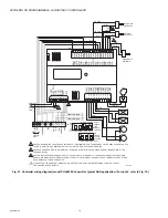
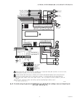
Страница 14: ...ations Typical controller wiring for VAV application using the TR23 Wall Module and a C7770A Air Temperature Sensor see Fig 18 on page 15 Typical controller wiring for VAV application with staged reheat see Fig 19 on page 16 Typical controller wiring for PWM reheat and PWM peripheral heat valve actuator see Fig 20 on page 17 Typical controller wiring for AHU application see Fig 21 on page 18 Typic...

Страница 15: ...OR CW COM CCW OCCUPANCY SENSOR CONTACTS CLOSED EQUALS OCCUPIED WINDOWS CONTACTS CONTACTS CLOSED EQUALS WINDOW CLOSED DI 2 COM 2 DO 5 DO 6 C7770A AIR TEMPERATURE SENSOR UI 3 COM AIR FLOW PICKUP ΔP 3 3 3 DAMPER OPEN DAMPER CLOSE REHEAT STAGE 1 OR OPEN REHEAT STAGE 2 OR CLOSE COM REHEAT STAGE 3 DI 3 COM COM SBUS1 SBUS2 AO 1 COM AO 2 AO 3 COM UI 1 COM UI 2 UI 3 COM UI 4 UI 5 COM UI 6 DI 1 DI 2 COM DI ...

Страница 16: ...CTS CLOSED EQUALS OCCUPIED WINDOWS CONTACTS CONTACTS CLOSED EQUALS WINDOW CLOSED DI 2 COM 2 AIR FLOW PICKUP ΔP 3 3 3 DI 3 COM LINE POWER STAGE 1 STAGE 2 STAGE 3 UI 3 AO 1 COM AO 2 AO 3 COM UI 1 COM UI 2 UI 3 COM UI 4 UI 5 COM UI 6 DI 1 DI 2 COM DI 3 20V DC DI 4 NET 2 NET 1 SHLD EGND 24 VAC 24VAC COM DO 1 COM DO 2 DO 3 DO 4 DO 5 COM DO 6 COM 1 2 3 4 5 6 7 8 1 0 9 2 3 4 5 6 7 8 0 9 1 1 1 1 1 1 1 1 1...

Страница 17: ...M OF 18 AWG 1 O MM2 FOR EARTH GROUND WIRE TO ASSURE PROPER ELECTRICAL CONTACT WIRES MUST BE TWISTED TOGETHER BEFORE INSERTION INTO THE TERMINAL BLOCK TURN POWER OFF BEFORE SETTING THE DIP SWITCHES MAKE SURE ALL TRANSFORMER POWER WIRING IS AS SHOWN REVERSING TERMINATIONS WILL RESULT IN EQUIPMENT MALFUNCTION M23573B 24 VAC 24 VAC COM DO 1 DO 2 DO 3 3 4 4 24 VAC COM 2 2 24 H 24 N PWM H 24 VAC PWM OUT...

Страница 18: ...OM 24 VAC 24 VAC COM DO 1 DO 2 DO 3 DO 4 DO 8 UI 3 COM 3 COM COM COM DISCHARGE AIR TEMP COM UI 6 OUTDOOR ENTHALPY RETURN ENTHALPY 20 VDC 20 VDC 3 499 2 COMP2 COMP 1 HEAT 2 HEAT 1 FAN UI 4 499 SBUS1 SBUS2 AO 1 COM AO 2 AO 3 COM UI 1 COM UI 2 UI 3 COM UI 4 UI 5 COM UI 6 DI 1 DI 2 COM DI 3 20V DC DI 4 NET 2 NET 1 SHLD EGND 24 VAC 24VAC COM DO 1 COM DO 2 DO 3 DO 4 DO 5 COM DO 6 COM 1 2 3 4 5 6 7 8 1 0...

Страница 19: ...I 3 COM 3 COM COM COM DISCHARGE AIR TEMP COM UI 6 OUTDOOR ENTHALPY RETURN ENTHALPY 20 VDC 20 VDC 3 499 2 COMP2 COMP 1 HEAT 2 HEAT 1 FAN UI 4 499 SBUS1 SBUS2 AO 1 COM AO 2 AO 3 COM UI 1 COM UI 2 UI 3 COM UI 4 UI 5 COM UI 6 DI 1 DI 2 COM DI 3 20V DC DI 4 NET 2 NET 1 SHLD EGND 24 VAC 24VAC COM DO 1 COM DO 2 DO 3 DO 4 DO 5 COM DO 6 COM 1 2 3 4 5 6 7 8 1 0 9 2 3 4 5 6 7 8 0 9 1 1 1 1 1 1 1 1 1 2 1 1 2 ...

Страница 20: ...AL BLOCK MAKE SURE ALL TRANSFORMER POWER WIRING IS AS SHOWN REVERSING TERMINATIONS WILL RESULT IN EQUIPMENT MALFUNCTION M29758 AO 1 DI 1 UI 1 UI 2 COM 24 VAC 24 VAC COM DO 1 DO 2 DO 4 3 COM DISCHARGE AIR TEMP AO 2 AO 1 COM AO 2 AO 3 COM UI 1 COM UI 2 UI 3 COM UI 4 UI 5 COM UI 6 DI 1 DI 2 COM DI 3 20V DC DI 4 NET 2 NET 1 SHLD EGND 24 VAC 24VAC COM DO 1 COM DO 2 DO 3 DO 4 DO 5 COM DO 6 COM 1 2 3 4 5...

Страница 21: ...following text for startup information Fig 25 LED service pin and network connection locations BROADCAST THE SERVICE MESSAGE The Service Message allows a device on the LONWORKS Bus to be positively identified The Service Message contains the controller s Neuron ID number and node type This is used to confirm the physical location of a particular Spyder Lon device in a building To send the Service ...

Страница 22: ...al block from its alignment pins 1 4 in 6 35 mm b For long terminal blocks 6 or more terminals insert screwdriver blade on one side of the terminal block and gently rotate the blade 1 4 turn Then move to the other side of the terminal block and do the same Repeat until the terminal block is evenly raised 1 4 in 6 35 mm from its alignment pins 2 Once the terminal block is raised 1 4 in 6 35 mm from...

Страница 23: ... Mount the new controller See Installation on page 4 6 Reconnect the two air flow pickup tubes to the pressure sensor See Piping PVL0000AS PVL4022AS PVL4024NS PVL6436AS and PVL6438NS on page 7 7 Replace the terminal blocks Insert each terminal block onto its alignment pins Press straight down to firmly seat it Repeat for each terminal block 8 Restore power to the controller 9 Perform Checkout on p...

Страница 24: ...ons Honeywell International Inc 1985 Douglas Drive North Golden Valley MN 55422 Honeywell Limited Honeywell Limitée 35 Dynamic Drive Toronto Ontario M1V 4Z9 customer honeywell com U S Registered Trademark 2009 Honeywell International Inc 63 2685 03 M S Rev 11 09 Printed in U S A ...

Отзывы: