SEC-H-600 SECURITY CONTROLLER
27
95-7759—07
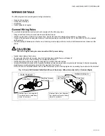
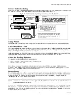
Connect the Backup Battery
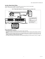
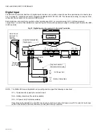
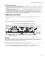
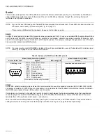
Connect the 12V sealed lead-acid Backup Battery to the 4-position connector next to the DB-9 connector, on terminals BT+ and
BT-. When the Security Controller is powered up, charging voltage is applied to the battery(ies).
Fig. 16. Sealed lead-acid backup battery connection on Security Controller.
Apply Power
Apply power to the Security Controller by energizing its connected SEC-ENC-H-1 or SEC-ENC-H-2 enclosure power supply.
Check the Status LEDs
When power is applied, the green LED labeled “STATUS” will light. This indicates that the system is OK and that power is applied.
Once the Security Controller boots, the yellow “BEAT” (heartbeat) LED will begin blinking, with a typical rate of about 1 Hz.
Blinking should begin within 30 seconds after power is applied.
If after applying power, the STATUS LED goes out, or if the BEAT LED comes on (steady) and stays lit longer than two minutes,
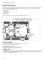
contact your Authorized Systems Distributor for technical assistance. Also see “Using Status LEDs,” page 30.
About the Backup Batteries
The Security Controller has two different backup batteries:
• An external (sealed lead acid) Backup Battery (or batteries), and
• An onboard NiMH battery pack.
Both batteries are required for system operation during loss of primary power (15Vdc power supply). Station alarms are
generated if either battery is uncharged or unable to hold a sufficient charge, as well as whenever primary power is lost. You
should always investigate any alarm related to backup batteries.
Backup Battery
The sealed lead-acid backup battery is an external, 12V, rechargeable battery (or multiple batteries) sized to operate the system
during loss of primary power, for some duration. This includes the Security Controller, including power to attached readers and
onboard relays, plus any “chained” expansion modules (and their attached readers and relays). For related details, see
“Estimating Power and Battery Requirements,” page 6.
NOTE: A maximum 2.5 A load can be powered through the PS-, PS+, BB terminals on the Security Controller. See “Maximum
Output Load Considerations,” page 8.
You connect the backup battery to the Security Controller using two terminals of a 4-position connector—see Fig. 16 on page 27.
Whenever primary-powered, the Security Controller supplies a constant “trickle” charge to this battery, at 200mA maximum. At
startup (boot), a test of the backup battery is performed, as well as a periodic test. A system alarm is generated if a battery test
deems the backup battery to be bad.
–
+
PS+
PS–
BT
+
BT
–
PS+
PS–
BB
RS-485
GN
D
SI
6
SI
1
SI
2
SI
3
SI
5
SI
4
GN
D
GN
D
15Vdc power and
backup battery passed
through end
connectors
NOTE:
Terminals BT+ and BT- of
Security Controller supply charging
voltage at maximum 200mA. This
trickle-charges the connected SLA
backup battery.
12V Sealed Lead
Acid Backup
Battery(ies)
Security
Controller
Battery harness supplied with SEC-ENC-H-1 and
SEC-ENC-H-2 enclosure has 0.25" (6.4mm) “fast
on” type spade connectors for connecting to 1 or
2 backup batteries.
WARNING:
A
maximum 2.5 A load
can be powered through the
PS-, PS+, BB terminals on the Security Controller.
A larger load will blow a soldered (unreplaceable)
2.5A fuse onboard the Security Controller.

