KNA Burner Manual 9.801-300.0 rev. 8/13
21
Start System
1. Make sure burner is powered.
2. Set thermostat to call for heat.
3. Make sure burner lights and operates until call
for heat ends. Note cad cell resistance while
running.
4. Verify that burner turns off when thermostat call
for heat is satisfied.
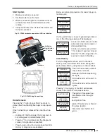
Fig. 12. R7284 terminals, connectors, LED, reset button
Home Screens
Pressing the "i" button longer than 2 seconds in
states other than Standby interrupts control opera-
tion.
Once the held key is released the count down be-
gins.
•
Holding all 3 buttons longer than 2 seconds in
any state goes to installer Setup (ISU).
•
Pressing "i" in any state enters the Diagnostic
screen (if diagnostics are enabled).
•
Pressing up or down in any screen enters Error
History (if diagnostics are enabled).
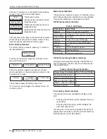
Below is a typical progression of screens through a
normal cycle.
If at any point there is an event generating a lockout,
one of the following screens will be displayed.
Control is in Soft Lockout. Control
will recover when error clears or
after specified time.
Control is in Hard Lockout. Hold
"i" for at least 2 seconds to reset.
Hold the "i" button longer than 10
seconds to return to Standby.
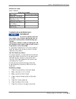
View History
From the Diagnostic screen, scroll to the View
History screen and select YES. Scroll through the
performance data by using the up or down buttons.
The CAD Cell screen automati-
cally scrolls 4 screens.
Average CAD cell value during
last cycle.
CAD cell trend over the last 10
cycles.
CAD cell trend over the first 500
cycles.
Pressing "i" during any of the CAD cell screens
moves to the Ignition Time screens below.
The Ignition Time screen au-
tomatically scrolls through 4
screens.
Last Ignition Time.
Ignition Time trend over the last
10 cycles. Ignition.
Time trend over the first 500
cycles.
Display
Up Button
Down Button
"i" button
Terminals
STANDBY
CALL FOR HEAT
IGNITION TRIAL
0:15
RUNNING
255 OHMS
SOFT LOCKOUT
15:00
HARD LOCKOUT
HARD LOCKOUT
CALL SERVICE
CAD CELL
LAST CYCLE
200 OHMS
LAST 10 CYCLES
250 OHMS
BASELINE
200 OHMS
IGNITION TIME
LAST CYCLE
11 SECONDS
LAST 10 CYCLES
11 SECONDS
BASELINE
8 SECONDS
Section: Honeywell Electronic Oil Primary
Fig. 13 R7284 Wiring Connections


