


N500-79-00 3 I56-1805-019
Step 1: Insert the bottom of the XP6-C module down into a rear slot on the
chassis.
Step 2: Carefully swing the upper edge of the board back towards the back of
the chassis until it touches the two standoffs.
Step 3: Align two 4-40 screws with the two standoffs and tighten.
Step 4: Address and wire the modules according to the instructions in this
manual.
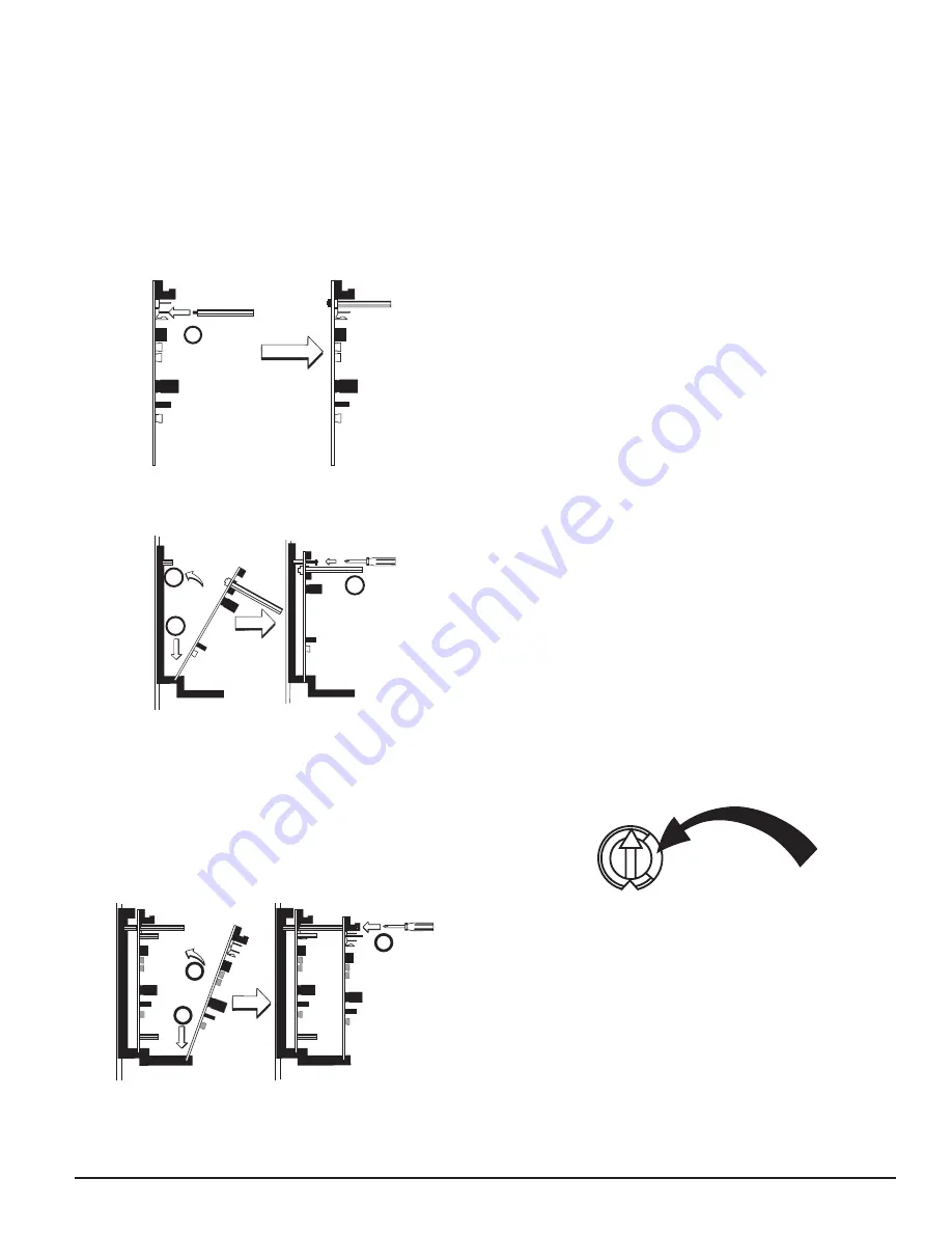
The steps in Figures 6A – 6C describe and illustrate module installation when
the rear chassis position and the position in front of it will be filled. Front
position installation is possible only if the rear position is filled with an XP
module.
FIGURE 6A: INSTALLATION OF XP6-C MODULE IN A REAR CHASSIS
POSITION, METHOD TWO
1
C0225-01
Step 1: Install two long standoffs in the lower mounting holes using two 4-40
nuts as shown.
FIGURE 6B.
3
2
4
C0249-01
Step 2: Insert the bottom of the XP6-C module down into a rear slot on the
chassis.
Step 3: Carefully swing the upper edge of the board back towards the back of
the chassis until it touches the two standoffs on the board.
Step 4: Align two 4-40 screws with the two standoffs on the chassis and
tighten.
Step 5: Address and wire the modules
according to the instructions in this manual.
FIGURE 6C: INSTALLATION OF XP6-C MODULE IN FRONT CHASSIS
POSITION
2
3
1
C0226-00
Step 1: Insert the bottom edge of the XP6-C module down into a front slot of
the chassis.
Step 2: Carefully swing the upper edge of the board towards the back of the
chassis until it touches the 11/4˝ (31.75mm) standoffs installed on
the rear module.
Step 3: Align two 4-40 screws with the two standoffs and tighten.
Step 4: Address and wire the modules according to the instructions in this
manual.
WIRING
NOTE:All wiring must conform to applicable local codes, ordinances, and
regulations.
1. Install module wiring in accordance with the job drawings and appropri-
ate wiring diagrams.
2. All wiring to the XP6-C is done via terminal blocks. In order to properly
make electrical connections strip approximately 1/4˝ of insulation from
the end of wire, sliding the bare end of the wire under the clamping plate
screw.
3. Set the address on the modules per the job drawing. Use the rotary code
switches to set the address of the first module (between 01 and 154).
To select Class B operation, install the J1 Shunt. The remaining modules are
automatically assigned to the next five higher addresses. For example, if the
base address switch is set to 28, the next five modules will be addressed to
29, 30, 31, 32, and 33.
To select Class A operation, remove the J1 Shunt. A maximum of three Class
A circuits are available. For example, if the base address switch is set to 28, 30
and 32 will be automatically assigned to the modules while 29, 31 and 33 are
available to be used for other modules on the SLC. For Class A and B opera-
tion, DO NOT set the lowest address above 154, as the other modules will be
assigned to nonexistent addresses.
NOTE: Some panels support extended addressing. In order to set the module
above address 99 on compatible systems, carefully remove the stop on the
upper rotary switch (see Figure 7). If the panel does not support extended ad-
dressing, do not set the lowest address above 94.
4. A shunt is provided to disable a maximum of three unused modules
(see Figure 8). Modules are disabled from the highest address and work
downward. If two modules are disabled, the lowest four addresses will
be functional, while the highest two will be disabled. For example, if
the shunt for Address Disable is placed on “two” and the base address
switch is set to 28, the modules will be assigned to 28, 29, 30 and 31,
disabling the highest two positions.
NOTE: In Class A operation, placing the small shunt on “disable 3˝ will dis-
able all three addresses. Placing the small shunt on “disable 2˝ will disable
two out of the three addresses. For example, if the address switch is set to
28 and the small shunt is placed on “disable 2˝, addresses 30 and 32 will be
disabled while address 28 will be enabled. The XP6-C must have power cycled
for shunt changes to take effect.
FIGURE 7:
TENS
0
7 8
6
5
4
3
2
1
9
10
11
12
13
14
15
C0227-00
5. There is an active short circuit protection option for each address. The
board is shipped with this option disabled for each address represented
by six large shunts on the “Disable Short Circuit Protection” area. To
enable short circuit protection for an address, remove the corresponding
shunts on the “Disable Short Protection” area. When enabled, this option
will isolate a short occurring on any active circuit allowing the remaining
circuits to continue normal operation.
NOTE: Power supply monitoring should not be used for audio applications.
The short circuit protection feature is also not available for audio applications.
NOTE: The XP6-C does not provide ring back when used as a firefighter tele-
phone circuit.
NOTE: Short circuit protection may only be enabled if power supply monitor-
ing is enabled.
NOTE: This feature is not for use with all Fire Alarm Control Panels. Please
consult with Technical Services before enabling this feature.
NOTE: Place unused shunts on single pin to store on board for future use.