Notifier FirstCommand Series Manual —
P/N LS10001-001NF-E:H 1/8/2018
45
Installation of Option Modules
Installation
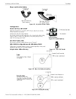
Power and Control Cables
Configuration
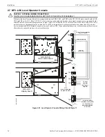
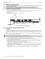
Enable Switches, SW6 & SW7
SW6 must be enabled.
Do not enable SW7
.
Do not confuse this switch from
SW6 on the main circuit board!
Switches come from the factory disabled.
Note that the board is installed upside-down. Pay close attention when setting
switches. Figure 2.36 shows the amplifier in its installed position, not the
actual silk-screening on the board.
FAIL TEST Switch, SW4
This switch is not used. It should always be set to “Normal”.
NFC-50/100 Configurations with NFC-BDA-25/70V
Following are descriptions of audio speaker circuit configurations with optional
amplifier and optional NFC-CE6 circuit expander.
Applications Without Backup
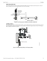
Control cable
p/n 75690
Align tab with notch in
board connector.
Tab
Power cable
p/n 75689
Align cable connectors
over spaces and pins.
Align where
there is no pin.
Figure 2.35 Control and Power Cables
Figure 2.36 Enable Switches
SW6 is shown enabled.
Do not enable.
Figure 2.37 FAIL TEST Switch
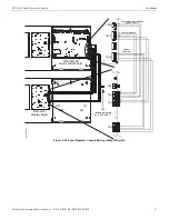
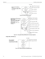
50W
circuit
1
Primary
• 50W
• One Class B or Class A Output
• No Backup
Figure 2.38 Basic (No Optional Amplifier)
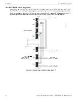
Primary
TB20 on main control board
Speaker Circuit Connection
zone button
50W
circuit
1
Primary/Secondary
• Two amps at 50W each
• Two Class B or Class A Outputs
• Optional amplifier is the secondary
• No Backup
Primary
50W
amp
Secondary
Figure 2.39 Primary/Secondary
2
TB20 on main control board
TB21 on main control board
Speaker Circuit Connections
zone button
Содержание Notifier FirstCommand Series
Страница 84: ...84 Notifier FirstCommand Series Manual P N LS10001 001NF E H 1 8 2018 Notes ...
Страница 86: ...Cut along dotted line ...
Страница 88: ...Cut along dotted line ...
Страница 92: ...92 Notes ...
Страница 94: ...Cut along dotted line ...
Страница 96: ...NOTIFIER 12 Clintonville Road Northford CT 06472 1610 USA 203 484 7161 www notifier com ...

