background image

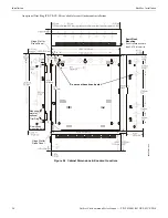
10

Notifier FirstCommand Series Manual —

 P/N LS10001-001NF-E:H 1/8/2018

+

+

+

J1

2

TB

1

5

J9

RT

Z

M

DI

SP

LA

Y

C

A

U

T

IO

N


 H

IG

H

 V

O

L

T

A

G

E

e

c

c

5

0la

y

o.

wm

f

AC

 P

o

wer

(S

up

er

vi

sed,

No

np

o

w

er

-L

imited

)

12

0 V

AC

, 6

0 H

z

, 3.5

 am

p

s

or

23

0 V

AC

, 5

0 H

z

, 2.0

 am

p

s

Spe

c

ia

l Applic

at

ion DC P

o

w

e

r O

u

tput

 (

2

4

 VDC)

S

u

pe

rvise

d

, P

o

we

r-L

imi

te

d

 (

Cla

s

s

 2

) circu

it

Su

p

e

rvi

s

e with

 a

 po

we

r sup

e

rv

isio

n re

la

E

O

LR

-1

No

nr

ese

tt

a

b

le P

o

w

e

r su

itab

le

 fo

r po

we

rin

g

 co

ntro

mo

du

le

a

n

d

 po

we

r sup

e

rv

isio

n re

la

ys.

NAC

 Followe

Input

S

u

p

e

rv

is

ed,

 Po

we

r-

Li

mit

e

d

 (Cla

s

s

 2)


cir

c

u

its

2

4 V

D

C

 fi

lt

er

ed

 (

10 

m

A

 ma

x

imu

m)

Re

qu

ire

s

 an

 FAC

P


En

d-

of-

L

in

e R

e

sist

or

AC

 Los

s, MN

S A

ct

ive

&

 Fix

e

d Tr

o

ubl

e Rel

a

y

No

n-s

u

p

e

rv

is

ed

 r

e

la

y

 c

o

n

tac

ts

Con

tac

t r

a

tin

g

:

2.0

 amp

s

 @ 3

0

 V

DC (re

sistive)

0

.5 a

m

ps @

 30

 VA

C

 (

re

s

is

ti

ve)

Co

nta

c

ts sh

own

 be

lo

w in 

no

rm

al co

nd

itio

n (A

C po

we

w

it

no

 al

ar

m

, tr

o

u

bl

e

, o

su

pervisory a

ctivity)

Fa

il S

a

fe

 Tr

oub

le r

e

la

switche

s

 to

 th

e NO 

positio

n


d

ur

ing tr

oub

le 

co

nd

it

io

ns and


un

d

e

r lo

ss of al

l po

wer

.

Fla

s

h Me

mor

y

 L

o

a

d

 En

ab

le


S

witch

: UP

 is no

rma

po

sition

 for

 switch

, DOW

N


po

sition 

allows fo

r fact

or

s

o

ft

wa

re

 up

gr

ad

es

E

the

rn

et

 Po

rt

 J

2

/

fo

r l

o

ca

pr

og

ra

mmin

g


usi

n

g a

 pe

rs

ona

c

o

mpu

ter

 a

n

we

b-

ba

sed

 ut

ili

ty

Ba

tt

ery

2

4

 V

DC, sup

e

rv

ised

No

n-

po

we

r-lim

ited

,

2

6

 A

H

 maxi

mum

Noti

fi

c

a

ti

on 

Applia

nce

 Circ

u

it

S

tyle Y (

Cla

ss 

B

) or 

S

tyle Z (Class A

Su

pe

rvise

d

, P

o

w

e

r-

Li

mit

e

d

 (Cla

s

s

 2) 

(Spe

ci

al


ap

pl

ic

at

io

n

) 2.

0


am

ps ma

x. 

Re

gu

la

te

d

 p

o

w

e

r: 

20

0m

A m

a

x.

EL

R

, 4.

7K,

 1/

2W

(fo

r Style

 Y wir

in

g)

O

p

ti

on

al

 5

0

W

 A

m

pl

if

ier


co

nne

ctors

Op

tiona

l 70

Tran

sfo

rmer co

nn

ecto

r

Op

tion

al CE6

 Ci

rc

u

it


E

x

pa

nd

e

r Con

n

e

c

to

r

Di

s

p

la

y

 Bo

ar

con

n

e

c

tor

S

p

e

a

k

e

r Volume Co

ntrol Ove

rride

St

yl

e

 Y 

(Class 

B) or S

tyle Z 

(Class 

A) 

S

upe

rv

ise

d,

 Pow

e

r-

L

im

ite

d (

C

la

ss 2

(S

pe

cia

l ap

pl

ic

ati

o

n)

 0.

25

 am

ps 

ma

x.

4.7

K

Ω

 ELR

, 1/2

W

 r

e

qui

red

 fo

r Styl

e Y 

(Cla

ss B)

 wirin

g

Pri

mary

/Se

condar

y

 S

p

e

a

k

e

r Ci

rcuits

Sty

le

 Y 

(Class 

B) or S

tyle Z (Class A

Su

pe

rvi

s

e

d, 

Pow

e

r-

Li

m

ited

 (

C

la

ss 2

5

0W

 i

nte

gr

ate

out

put

 po

w

er

. U

s

of 

se

con

d

a

ry 

ci

rcu

it

 requ

ir

e

s

 op

tion

al 

NFC-

BD

A-2

5

/7

0

V

 a

mpl

ifier

15

K

Ω

 ELR

, 1W

 r

equ

ir

e

d for

 St

yle

 Y 

(Cl

a

ss B

) wirin

g

C

M

D1 & 

CM

D2

 Command Input

 C

ircuits

Tr

ig

ge

r by 

con

tact

 cl

osu

re

 o

N

A

C

 r

e

ve

rs

po

lar

it

y

 (

E

L

R

 re

qu

ire

d

 f

o

me

ssag

e

s)

al

ar

m po

lar

it

y

 s

h

o

w

n.

C

M

D3

 -

 C

M

D8 

Co

m

m

and Input Circ

uits

Tri

g

ger

 b

y

 co

nta

c

t cl

osu

re

 (

EL

R

 re

qu

ir

e

d


fo

r me

ssag

e

s)

 a

la

rm p

o

la

ri

ty sh

own

.

(i

npu

ts o

n

ly

)

N

igh

t Ring 

Input

Tr

ig

ge

r b

y

 co

nta

c

t closu

re

Ex

te

rnal 

Opera

tor

 Int

e

rf

ac

e P

o

wer

S

u

pe

rvise

d

, Po

we

r-L

imi

te

d

(C

la

ss 2) circuit

2

4

 V

D

C No

nr

ese

tta

bl

e Pow

e

r for


e

x

te

rn

al

 o

p

e

ra

to

r i

n

te

rf

ace

 co

mp

on

e

n

ts

.

Ex

te

Arnal Da

ta

 Bu

s

S

u

pe

rvise

d

, Po

we

r-L

imi

te

d


(C

la

ss 

2

) da

ta con

n

e

c

tion

to


e

x

te

rn

al

 o

p

era

tor

 i

nt

er

fac

e


c

o

mp

on

en

ts

FACP

 D

a

ta

 Bus

Su

pe

rvi

s

e

d, Pow

e

r-

Li

m

ited


ci

rcu

it d

edi

ca

ted

 as 

FAC

P


se

ri

a

l bu

s con

n

e

c

tion


Exte

rnal Audio 

R

iser

Style

 Y (Class B

) or St

yl

e

 Z (Class A

S

u

p

e

rv

ised

, Po

we

r-L

imite

d

 (Cl

a

ss 2

a

udio

 con

n

e

c

tion

 to 

exte

rn

al o

p

e

ra

tor


in

te

rf

a

c

e c

o

mp

on

en

ts


Sp

eake

V

ol

tag

S

witch

SW

5

To

 di

sab

le 

gr

ou

nd fau

lt 

de

te

c

tio

n,


re

move


ju

m

p

er

/s

h

u

n

fr

om J

S

2.

NFC

-50

/10

0


Tr

ou

bl

e LE

D

s

See


S

e

ctio

n

1

.3.

3


on

 pa

ge

18 f

or


mo

re


in

for

m

atio

n

.


Basic Syst

em C

onn

ectio

ns -

 Main C

o

n

trol B

o

ard (

S

ectio

n

1.2.1

)

Cut 

ju

m

p

er

 t

o

 u

s

exte

rn

al

 ch

ar

ge

r

B

a

cku

p a

m

p

lifier


te

st switch

 SW6

Se

t switch 

to 

No

rm

a

l

(d

ow

n posi

ti

o

n)

US

B-

A P

or

t J1

/

fo

r lo

cal p

ro

g

ra

d

o

wnlo

a

d

Содержание Notifier FirstCommand Series

Страница 1: ...Document LS10001 001NF E Rev H 1 8 2018 ECN 18 117 Notifier FirstCommand NFC 50 100 NFC 50 100E Instruction Manual ...

Страница 2: ... may not provide adequate warning of a fire Smoke detectors cannot be expected to provide adequate warning of fires caused by arson children playing with matches especially in bedrooms smoking in bed and violent explosions caused by escaping gas improper storage of flammable materials etc Heat detectors do not sense particles of combustion and alarm only when heat on their sensors increases at a p...

Страница 3: ...o do so can damage circuits Remove all electronic assemblies prior to any drilling filing reaming or punching of the enclosure When possible make all cable entries from the sides or rear Before making modifications verify that they will not interfere with battery transformer or printed circuit board location Do not tighten screw terminals more than 9 in lbs Over tighten ing may damage threads resu...

Страница 4: ...he appropriate version for a specific application Documentation Feedback Your feedback helps us keep our documentation up to date and accurate If you have any comments or suggestions about our online Help or printed manuals you can email us Please include the following information Product name and version number if applicable Printed manual or online Help Topic Title for online Help Page number fo...

Страница 5: ...2 External Audio Input 29 2 5 3 NAC Follower Input 29 2 5 4 Night Ring 30 2 6 Output Circuits 30 2 6 1 Relays 30 MNS Active Relay TB1 30 Trouble Relay TB2 31 AC Power Loss Relay TB3 31 2 6 2 Speaker Circuits 31 2 6 3 Notification Appliance Circuit 32 2 6 4 Speaker Volume Control 33 2 6 5 FACP Data Bus 34 NFW 100X 34 FireWarden 100 2 34 NFS2 640 and NFS 320 35 ACS Mode Wiring 35 2 7 NFC LOC Local O...

Страница 6: ...ecific 66 FACP Message Assignment Zone Specific 66 FACP Programming Menus 67 3 6 2 NFS2 640 and NFS 320 68 FACP Programming 68 Section 4 Operating Instructions 70 4 1 Main Control Panel Keypad Labels 70 4 2 NFC 50 100 Switch Functions 70 4 3 LED Indicators 71 4 4 Operation 72 4 4 1 Paging from the Microphone 72 4 4 2 Manual Message Control 72 4 4 3 Fire Alarm Response System Configured for Fire On...

Страница 7: ...raw 78 6 3 1 Overview 78 6 3 2 How to use Table 6 2 to calculate system current draws 78 6 4 Calculating the Battery Size 80 6 4 1 NFPA Battery Requirements 80 6 4 2 Selecting and Locating Batteries 80 Appendix A Digital Voice Messages 81 Appendix B Wiring Requirements 82 Appendix C Canadian Applications 83 C 1 Audio Room Isolator Modules 83 C 1 1 Description 83 C 1 2 Panel Programming 83 C 1 3 Ap...

Страница 8: ...naling Systems UL 1971 Signaling Devices for Hearing Impaired UL 2572 Communication and Control Units for Mass Notification Systems CAN ULC S524 01 Standard for Installation of Fire Alarm Systems CAN ULC S527 11 Standard for Control Units for Fire Alarm Systems This Class A digital apparatus complies with Canadian ICES 003 Cet appareil numérique de la classe A est conforme à la norme NMB 003 du Ca...

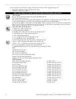
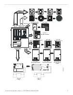
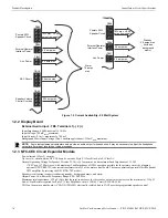
Страница 9: ...pander NFC 50DA 50W remote amplifier NFC RPU remote page unit NFC RM remote microphone remote consoles distributed audio NFC 125DA 125W remote amplifier NFC LOC local operator console CHG 120 charger CHG 75 charger external battery charger J7 TB24 TB12 TB22 nfcperi wmf NAC Circuit TB19 visual only NFC FFT firefighter telephone NFC 50 100DA 50 100W remote amplifier ...

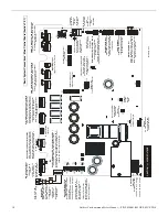
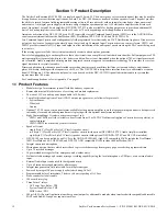
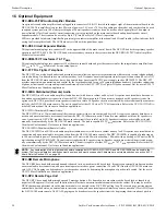
Страница 10: ...6 Circuit Expander Connector Display Board connector Speaker Volume Control Override Style Y Class B or Style Z Class A Supervised Power Limited Class 2 Special application 0 25 amps max 4 7KΩ ELR 1 2W required for Style Y Class B wiring Primary Secondary Speaker Circuits Style Y Class B or Style Z Class A Supervised Power Limited Class 2 50W integrated output power Use of secondary circuit requir...

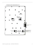
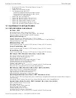
Страница 11: ...rce other than main control board J2 Connection to main control board P2 Microphone connector J1 USB connector connection to a PC for downloading messages Refer to Section 3 5 5 on page 63 Basic System Connections Display Board Section 1 2 2 disp wmf SW2 Distributed Audio Switch set to UP position if any NFC 50 125DAs are installed in the system Default is the DOWN position JP2 External Data Bus t...

Страница 12: ... tional CMD inputs 1 8 fire alarm control panels or can be used with the NFC 50 125DA panel to distribute audio in systems that require more than 100 watts For Canadian applications refer to Appendix C on page 83 1 1 Product Features Modular design for maximum system flexibility and easy expansion Removable terminal blocks for ease of servicing and module replacement 50 watts of 25 VRMS audio powe...

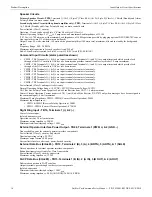
Страница 13: ...C Loss Relay TB3 Form C relay contact rating 2 0 amps 30 VDC resistive 0 5 amps 30 VAC resistive NAC Output TB19 Terminals 1 B 2 A 3 A 4 B One 1 Style Y Class B or Style Z Class A circuit Power limited circuitry Class 2 supervised Nominal operating voltage 24 VDC Maximum signaling current for special application power 2 0 amps Maximum signaling current for regulated power 200mA Current limit fusel...

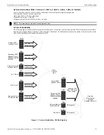
Страница 14: ...sure only CMD5 TB7 Terminals 1 2 are input terminals for contact closure only CMD6 TB7 Terminals 3 4 are input terminals for contact closure only CMD7 TB8 Terminals 1 2 are input terminals for contact closure only CMD8 TB8 Terminals 3 4 are input terminals for contact closure only Power limited Class 2 and supervised circuitry Normal Operating Voltage Range 10 5 VDC 29 VDC Maximum Voltage 29 VDC N...

Страница 15: ...ower Supply Calculations for additional current draw by option cards that must be consid ered when determining total standby and alarm currents NOTE Zero impedance to ground will cause a ground fault TB20 TB21 TB19 TB24 TB23 TB17 Primary 50W Speaker Circuit 50W max 3 3 amps from supply Secondary 50W Speaker Circuit Optional Amplifier Installed NAC Circuit 2 0 amps max Aux Power 0 5 amp max Speaker...

Страница 16: ...r circuit wiring is supervised during standby background music and alarm Output Power 50 watts total Frequency Range 800 2 800 Hz Maximum total capacitance 250 µF Note that the total capacitance for the speaker outputs must not exceed the maximum of 250 µF End of Line Resistor required for Style Y Class B speaker circuit 15 KΩ 1 watt P N ELR 15K TB13 on the main control board ACS ANN EIA 485 elect...

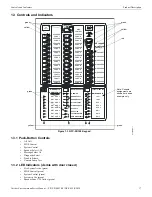
Страница 17: ...Note Console assignments are shown here as an example only SPEAKER ZONE 1 SPEAKER ZONE 2 SPEAKER ZONE 3 SPEAKER ZONE 4 SPEAKER ZONE 5 SPEAKER ZONE 6 SPEAKER ZONE 7 SPEAKER ZONE 8 SPEAKER ZONE 9 SPEAKER ZONE 10 SPEAKER ZONE 11 SPEAKER ZONE 12 SPEAKER ZONE 13 SPEAKER ZONE 14 SPEAKER ZONE 15 SPEAKER ZONE 16 SPEAKER ZONE 17 SPEAKER ZONE 18 SPEAKER ZONE 19 SPEAKER ZONE 20 SPEAKER ZONE 21 SPEAKER ZONE 2...

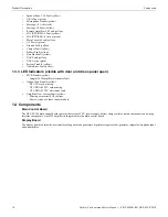
Страница 18: ...ndicators visible with door and dress panel open MCB Trouble yellow Integral 50W amplifier electronics fault Option Card Trouble yellow NFC CE6 card missing NFC BDA 25 70V card missing NFC BDA 25 70V electronics fault Amplifier Over Current Fault yellow Missing or incorrect EOL resistor Short circuit on volume control module 1 4 Components Main Control Board The NFC 50 100 main control board conta...

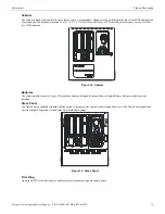
Страница 19: ...or two 12AH or two 18AH batteries Batteries The cabinet provides space for up to 18 Amp Hour batteries charged by integral Power Supply Battery Charger with all options installed Dress Panel The Dress Panel is supplied standard with the system It mounts to the cabinet with two supplied screws The Dress Panel protects the user from high voltages and circuit boards from accidental damage Trim Ring A...

Страница 20: ... The unit is capable of either 25 VRMS or 70 7 VRMS operation Refer to the NFC 50 125DA Dis tributed Audio manual Not for use in Canadian applications NFC 125DA Distributed Remote Audio The NFC 125DA is a 125 watt audio amplifier audio booster with its own cabinet and key lock It requires an external data bus con nection and an external audio riser connection from the NFC 50 100 main console The u...

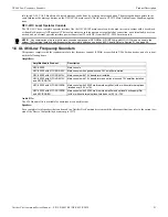
Страница 21: ...ers Audio File The 520 Hz audio file is available for download at esd notifier com Speakers For a complete list of speakers that can be used in a Notifier FirstCommand system with the above specifications refer to the current ver sion of the Device Compatibility document p n 15378 NOTE Any combination of up to eight remote consoles comprised of NFC RM s NFC RPU s and NFC LOC s can be used in the s...

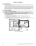
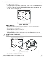
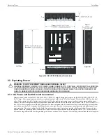
Страница 22: ... wiring should be in accor dance with the National and or Local codes for fire alarm systems Refer to Figure 2 4 for knockouts that cannot be used 2 2 Backbox Installation Removing the Dress Panel 1 Open the door and lift the door off the pin hinges 2 Loosen the two 2 screws that secure the dress panel to the backbox Then lift up to swing the dress panel open 3 Disconnect the ground wire from the ...

Страница 23: ...tener in the wall with the screw head protruding 3 Place backbox over the top screw level and secure 4 Mark and drill the left and right upper and lower mounting holes Note Outer holes closest to sidewall are used for 16 O C stud mounting 5 Install remaining fasteners and tighten 6 Carefully reinstall the chassis assembly and dress panel by reversing the steps above Use appropriate precautions to ...

Страница 24: ...TR CE B is available for semi flush mount installations Figure 2 4 Cabinet Dimensions Knockout Locations 9050udencl wmf Semi Flush Mounting Do not recess box more than 3 875 into wall to Hinge Slot for Dress Panel Hinge Slot for Dress Panel Semi flush mounting hole Mounting slots for optional Trim Ring Do not use these knock outs ...

Страница 25: ...nnect devices A separate Earth Ground connection must be made to ensure proper panel operation and lightning and tran sient protection Do not use conduit for the Earth Ground connection since this does not provide reliable protection Remove the two keps nuts from the grounding stud in the backbox Connect the incoming earth ground wire to supplied cable 71073 with a wire nut Position the ring termi...

Страница 26: ...he stud Apply AC power to the panel only after the system is completely installed and visually checked Note that AC power must be applied to the panel before installing the battery interconnect cable refer to the fol lowing section Figure 2 6 Earth Ground Connection eccgnd wmf grounding stud keps nuts Grounding Cable 71073 grounding stud Equipment Ground ...

Страница 27: ... is in alarm See page 78 for calculation of the correct battery rating 2 4 Auxiliary DC Power Output Connections The Special Application Auxiliary DC power output is power limited Class 2 WARNING RISK OF PERSONAL INJURY BATTERY CONTAINS SULFURIC ACID WHICH CAN CAUSE SEVERE BURNS TO THE SKIN AND EYES AND CAN DESTROY FABRICS IF CONTACT IS MADE WITH SULFURIC ACID IMMEDIATELY FLUSH THE SKIN OR EYES WI...

Страница 28: ...series with its OUT terminals which are used in the reverse polarity configuration to open the outgoing NAC circuit during an NFC 50 100 trouble condition In standby this generates a NAC trouble at the host FACP feature is bypassed in alarm condition These contacts do not open during AC loss at the NFC 50 100 however they are fail safe meaning that a complete loss of power there will open the circ...

Страница 29: ...00 Auxiliary Power output and the control module with an EOL relay EOLR 1 3 End of Line resistor supplied with modules 2 5 2 External Audio Input The display provides connection to various ancillary sources See Sections 2 5 4 on page 30 3 5 2 on page 61 and 4 4 15 on page 76 for more information 2 5 3 NAC Follower Input For fire only applications the NAC follower input may be used to trigger the o...

Страница 30: ...2 2 for electrical specifications to the external audio input 2 6 Output Circuits 2 6 1 Relays MNS Active Relay TB1 The main control board provides a Form C MNS Active relay The MNS Active Relay will transfer state when any Mass Notification MNS event occurs The system must be enabled for Mass Notification in programming for use of this relay from FACP NAC or NAC Follower output or previous device...

Страница 31: ...BDA 25 70V and NFC CE6 The integral amplifier and optional amplifier each provide audio for one Speaker Circuit The circuit can be wired Style Y Class B or Style Z Class A Each supervised and power limited Class 2 circuit is capable of 50 watts of power Refer to the Notifier Device Compatibility Document for a listing of compatible speakers Shielded cable is not required however shielded cable wil...

Страница 32: ...ted 24 VDC visual notification appliances only Circuit is supervised and power limited Class 2 Refer to the Notifier Device Compatibility Document for a listing of compatible notification appliances ELR 4 7K 1 2W for Class B Style Y wiring TB19 Polarized Bell Polarized Strobe Polarized Horn Figure 2 16 NAC Wiring Style Y Class B eccnac wmf TB19 Polarized Bell Polarized Strobe Polarized Horn Figure...

Страница 33: ...he SP SVC in the speaker circuit Any speakers placed after the SP SVC module will be able to be attenuated 3 An end of line resistor ELR must be installed on the last speaker connected to the SP SVC 4 Attach wires according to the label on the terminal block The DC input output terminals are interchangeable If the SP SVC is the last unit in the Speaker Volume Control Override circuit then an ELR m...

Страница 34: ...n 100 2 The FireWarden 100 2 FACP communicates with the NFC 50 100 over the ACS or ANN BUS annunciator link Wiring must be con nected between Terminal TB9 on the FACP and Terminal TB13 on the NFC 50 100 panel 24V SLC ANN BUS PRI ANN BUS SEC A B TB9 TB10 A B Figure 2 19 Connection for NFW 100X to NFC 50 100 NFC 50 100 to other ANN devices esecc wmf NFW 100X TB9 or TB10 B A B A A B ACS SHIELD SLC SL...

Страница 35: ...s wired over the ACS annunciator link a monitor module must be used to monitor mass notification events Wire the monitor module to the NFC at TB1 MNS Active Relay in addition to the Data Bus wiring shown above Refer to FACP Program ming on page 68 for information on type IDs Figure 2 21 ACS Connection for NFS2 640 or NFS 320 to NFC 50 100 to other ACS devices located down stream NFS2 640 or NFS 32...

Страница 36: ...own below For the external audio riser when the LOC is the last device termination ELR 15K must be connected to pins 5 and 6 on TB5 T taps and multiple home runs to the main control board are not allowed for the external data bus or the external data riser CAUTION EXTERNAL WIRING CONNECTIONS THE NFC LOC IS A SEPARATE DEVICE NOT PART OF THE NFC 50 100 ASSEMBLY J12 TB15 J9 RTZM Rev ECC MCB PCA B A B...

Страница 37: ...12 TB15 J9 RTZM Rev ECC MCB PCA B A B A B A B A TB24 TB12 TB22 TB3 TB4 TB5 external operator interface power 24VDC external data bus external audio riser locwirea2 wmf Figure 2 24 Local Operator Console Wiring Class A Style Z TB2 JP2 shown jumpered on pins 2 and 3 NFC 50 100 main control board NFC LOC display board ...

Страница 38: ...umper must be on pins 2 and 3 of JS4 as shown below For the external audio riser when the NFC RPU is the last device termination ELR 15K must be connected to pins 4 and 5 on TB2 T taps and multiple home runs to the main control board are not allowed for the external data bus or the external data riser B A B A B A main control board RPU board TB24 TB12 TB22 TB1 TB3 TB2 external operator interface p...

Страница 39: ...Remote Page Unit Installation B A B A B A B A main control board RPU board TB24 TB12 TB22 TB1 TB3 TB2 external operator interface power 24VDC external data bus external audio riser rpuwirea wmf Figure 2 26 Remote Page Unit Wiring Class A Style Z JS4 shown jumpered on pins 2 and 3 ...

Страница 40: ...he external data bus or the external data riser 2 10 NFC 50DA NFC 125DA NFC 50 100DA Distributed Audio Amplifiers SW2 on the NFC 50 100 s display board must be set to the UP position if any remote audio boosters are installed on the system Refer to the NFC Distributed Audio Amplifier Manual LS10027 001NF E for installation instructions B A A B A B main control board RM board TB24 TB12 TB22 TB3 dat...

Страница 41: ... not touch anything If mul tiple external devices are used in the system then the shields must pass through connect to the outgoing shield using wire nuts without touching anything else For Class A Style Z installations the shield from the last external operator interface must be connected to the same NFC 50 100 terminal that the shield originated from NOTE Never use a cable shield as an enclosure...

Страница 42: ... limited circuit wiring must enter and exit the cabinet through different knockouts and or conduits A typical wiring diagram for the NFC 50 100 with two speaker circuits is shown below Figure 2 31 Typical Wiring Diagram for UL Power limited Requirements Power limited Circuits Class 2 ecculpwr wmf Power limited Circuits Class 2 Power limited Circuits Class 2 AC Power Nonpower limited Circuit Power ...

Страница 43: ...lifier Module with the screws removed in Step 1 It is important to secure the module with the metal screws in order to help protect against electrical transients 4 Plug the supplied power cable into J10 on the main control board then into J1 on the audio amplifier Plug the supplied control cable into J11 on the main control board then into J2 on the audio amplifier 5 Configure the slide switches S...

Страница 44: ...opulated on 70V boards NOT USED LED1 Power BDA Power BDA Control Connect J1 to J10 Connect J2 to J11 J12 TB15 J9 RTZM Rev ECC MCB PCA P1 J12 TB15 J9 RTZM Rev ECC MCB PCA 1 Attach four standoffs p n 42227 at locations indicated 2 Align amplifier over standoffs Attach with four screws 3 Attach power harnesses included with amplifier refer to Figure 2 35 Power and Control Harness Connections Amplifie...

Страница 45: ...aker circuit configurations with optional amplifier and optional NFC CE6 circuit expander Applications Without Backup Control cable p n 75690 Align tab with notch in board connector Tab Power cable p n 75689 Align cable connectors over spaces and pins Align where there is no pin Figure 2 35 Control and Power Cables Figure 2 36 Enable Switches SW6 is shown enabled Do not enable Figure 2 37 FAIL TES...

Страница 46: ... or Class A Outputs Optional amplifier supplies all secondary circuits NFC CE6 adds 3 primary and 3 secondary circuits No backup Primary 50W amp Secondary Figure 2 41 Primary Secondary with Expander and Optional Amplifier CE6 5 6 7 8 TB20 on main control board TB21 on main control board TB1 on NFC CE6 primary power TB4 on NFC CE6 secondary power TB2 on NFC CE6 primary power TB5 on NFC CE6 secondar...

Страница 47: ...what other option modules are installed See the NFC XRM 70V Installation Document Refer to the drawing below 50W circuit 1 2 3 4 Primary with Expander and Backup 50W for primary 50W for backup Four Class B or Class A Outputs NFC CE6 adds 3 primary speaker circuits Optional Amplifier is the backup Primary Figure 2 43 Primary with Expander and Optional Amplifier Backup CE6 Primary Backup 50W amp Bac...

Страница 48: ...te that these four 4 consoles occupy two 2 data bus addresses each The second address is already reserved in the system for each console Up to eight 8 distributed amplifiers NFC 50DA and NFC 125DA can be used in the system Their external data bus addresses must also be unique and sequential All addressing must also be set in user programming Refer to Section 3 2 3 on page 55 Bus Address Device Dip...

Страница 49: ...ed in the cabi net Pay close attention when setting addresses Bus Address Device Dipswitch Setting on NFC 50DA SW1 Dipswitch Setting on NFC 125DA SW1 Dipswitch Setting on NFC 50 100DA SW3 20 External Amp 1 21 External Amp 2 22 External Amp 3 23 External Amp 4 24 External Amp 5 25 External Amp 6 1 2 3 4 5 6 ON 1 2 3 4 5 ON 1 2 3 4 5 6 7 8 ON 1 2 3 4 5 6 ON 1 2 3 4 5 ON 1 2 3 4 5 6 7 8 ON 1 2 3 4 5 ...

Страница 50: ...essing External Data Bus Devices 26 External Amp 7 27 External Amp 8 Bus Address Device Dipswitch Setting on NFC 50DA SW1 Dipswitch Setting on NFC 125DA SW1 Dipswitch Setting on NFC 50 100DA SW3 1 2 3 4 5 6 ON 1 2 3 4 5 ON 1 2 3 4 5 6 7 8 ON 1 2 3 4 5 6 ON 1 2 3 4 5 ON 1 2 3 4 5 6 7 8 ON ...

Страница 51: ...rd Securely configure networks and firewalls Assess security risks Develop a Disaster and Recovery Plan Develop a Backup and Recovery Strategy Install configure and maintain anti virus software on all computers which access the panel Keep the operating system updated and maintain version compatibility with the panel Deliver all required system information upon delivery to the system owner Train en...

Страница 52: ...rd The default password for the NFC 50 100 is 0000 New Password It is recommended that the password be changed to increase system security Valid passwords contain four digits from 0000 9999 Verify New Password Re enter the new password for confirmation Inactivity Timeout Select the amount of time 5 minutes 10 minutes 20 minutes 30 minutes or 60 minutes the system is allowed to remain idle before a...

Страница 53: ...Canadian requirements See Appendix C for more information Class A Style Z Select enable if all circuits on the NFC will operate in Class A Style Z or disabled if all circuits will operate in Class B Style Y Canadian Isolator Modules If audio isolator modules are required in the system select enabled Refer to Audio Room Isolator Mod ules on page 83 for more information AC Loss Delay The reporting o...

Страница 54: ... the NFC and the maximum number that can be connected to each NAC Make sure that the NAC maximum current is not exceeded Aux Power Selects whether this power is Constant or Resettable use from TB17 Speaker Volume Control NAC If the Cooper Wheelock SP SVC module is installed on TB23 of the main control board allowing man ual volume setting for telephone paging and background music for a specific sp...

Страница 55: ...alled at addresses 4 6 8 10 12 14 16 and 18 as either Local Operator Console or Remote Microphone Note that the NFC RPU and NFC RM are both considered remote microphones Refer to Section 2 14 Addressing External Data Bus Devices for information on dipswitch settings Note that Address 2 is reserved for the POC Mic Gain is the microphone s transmitting volume control The gain number is automatically...

Страница 56: ...e system 70VAC Option For every programmed 50W remote amplifier select whether a 70V transformer has been Installed or Not Installed 70V operation is not available on the 125W model 3 2 4 Message Buttons Message Buttons Assignment Message buttons 1 14 can be used to broadcast prerecorded messages over the system They must be designated as Fire Evacuation or Mass Notification in the Assignment fiel...

Страница 57: ... Send to Panel button to save changes to the panel Selecting the Load Defaults button will apply default programming to the given page To then save the applied default settings to the panel press the Send to Panel button The Main Menu button will disregard any programming selections and jump back to the main menu screen Changes made to panel programming will not be applied until complete log out o...

Страница 58: ...ecording must then be disabled Simply click the Disable Recording button 3 3 2 USB File Options The NFC system allows software files to be saved shared and transferred via the computer s USB port The program file must be named CONFIG TXT When saving the program file to USB it is vital that no other files with the same name exist on the drive The existing file will be completely overwritten Only fi...

Страница 59: ... The Speaker Circuit Button Assignment page reflects what has been programmed into the Address Assignment page Refer to Speaker Circuit Address Assignment on page 55 Based on the example above the NFC system s primary operator console has four 4 pro grammed speaker circuits a remote amplifier at address 20 has two 2 speaker circuits and a second remote amplifier at address 21 has three 3 speaker c...

Страница 60: ...n shows the system s event history A maximum of 100 events can be viewed starting with the most recent This information can be erased by clicking the Clear History button Clicking the Print button will activate the print dialog box Print options are selected in this box Note that the Date and Time in the heading of the print screen correspond to those of the panel and not the computer The Unit ID ...

Страница 61: ...ed to control the recording erasing process When in Local Record mode the display board s LEDs will function as follows 3 5 2 External Audio Input The external audio input allows customized pre recorded messages to be loaded into a message slot 1 Wire a speaker cable with 1 8 mini plug Radio Shack p n 42 2454 to EXT Audio GND and IN terminals on the display board 2 Plug the mini plug into the Line...

Страница 62: ... start recording When the PC message is done press zone button 19 again to stop recording The yellow zone LED 2 will stay lit until completed The green LED for zone button 2 will light after the recording is complete Enter programming mode again and deselect Message Record Mode 3 5 3 Microphone Messages can be recorded into the system using the onboard microphone 1 Enter programming mode at the ma...

Страница 63: ...User Message Messages stored in message slots 1 14 can be erased 1 Enter programming mode at the main control board 2 Enable Recording Mode in the system s message recording programming section Refer to Section 3 5 1 on page 61 The display board will then light the green zone 1 14 LEDs for all message slots that contain messages 3 Press zone button 24 on the display board then zone button 1 14 for...

Страница 64: ...the user if there is no message stored blank in the selected message slot location 4 Repeat steps 1 through 3 for any addition messages to be read or close VL software if finished Moving a Message to a Different Slot To move a message from one message slot location to another first read the desired message from its current message location into the PC and then write this message file from the PC t...

Страница 65: ...on is when one or more devices programmed to Zones 33 through 40 is also activated If the newly activated zone is programmed to a message with a higher priority then Zone 32 the higher pri ority message will be generated to all circuits Note 2 Messages have a priority scheme with Message 1 having the highest priority and Message 14 having the lowest priority For example If an addressable device ac...

Страница 66: ...e 1 in example below will be generated over all speaker circuits FACP Message Assignment Zone Specific The FACP can be programmed to allow a specific addressable input device to generate one of fourteen messages over any speaker cir cuit Any one of the fourteen messages can be programmed to each of the available zones Zone 1 through Zone 99 In the following example assume that Zone 5 is programmed...

Страница 67: ...ng Mode by pressing the 2 key The following screen will be displayed Entering the Master level password default 00000 will cause the following screen to appear Select the Zone Setup option by pressing 3 The following screens will be displayed Pressing 3 while viewing Zone Setup Screen 3 will cause the following screen to be displayed Zone 5 and Zone 35 Zone 7 and Zone 35 Addressable Pull Station a...

Страница 68: ... Annunciator Group M must be selected for annunciator address number 1 in FACP programming using VeriFire Tools FACP Programming The NFS2 640 or NFS 320 must be programmed to operate with the NFC 50 100 The following table summarizes the steps involved in programming the FACP ACS Annunciator The NFC 50 100 communicates with the FACP via the ACS link Enable the ACS Annunciator as described in the N...

Страница 69: ...ed to A1p11 and A1p40 A general alarm will play message 1 and activate an all call on the FirstCommand VeriFire Tools must be used for speaker and circuit and message control IMPORTANT Messages have a priority scheme with Message 1 having the highest priority and Message 14 having the lowest priority The highest priority message will always be generated over all activated speaker circuits FireVoic...

Страница 70: ...for equal priority then the ALL CALL will only occur when the system is not already in use System in Use LED is not on remote console active LED is not on Refer to the SYSTEM CONTROL button description When the operator completes the page any previously interrupted emergency broadcast will resume Previously initiated emergency broadcast will also resume after the push to talk PTT switch is held fo...

Страница 71: ...is selected those fault LEDs represent the main console status Trouble Silence This button is used to manually silence the local trouble sounder Console Lamp Test This button is used to test the console LEDs and local sounder When pressed all LEDs temporarily light and the local sounder is turned on temporarily 4 3 LED Indicators Refer to Figure 1 3 NFC 50 100 Keypad on page 17 Fire System Active ...

Страница 72: ...rcuits are off and all relays are in their normal state 4 4 1 Paging from the Microphone 1 The NFC 50 100 main console must be in control of the system to perform a page If the green System in Use LED is lit press the SYSTEM CONTROL button The NFC 50 100 is ready to page once the System in Use LED turns off and the System Control LED lights steady If the System Control LED is already lit this acti...

Страница 73: ...tton the system will Turn the appropriate speaker zone LED s on steady Turn the appropriate speaker circuit s on Turn the appropriate message LED on steady Turn the appropriate audio amplifier s on Turn the 24 VDC aux power output on if programmed Turn the speaker volume control override on Turn the System in Use LED on steady Activate the MNS active relay if the system is programmed for mass noti...

Страница 74: ...System Configured for Combo Fire Mass Notification with Fire Priority If the restoral is for a fire alarm only under this configuration then the system will respond as in Section 4 4 4 above If the restoral is for a mass notification alarm alert only under this configuration then the system will respond as in Section 4 4 8 above and additionally will Signal the FACP of the restoral using the FACP ...

Страница 75: ...ssociated peripheral console fault LED turns on steady For a distributed amplifier fault the associated distributed fault LED turns on steady For distributed amplifier faults the following will occur on the display when the operator uses the DIAGNOSTIC button to select a dis tributed amplifier for more specific indication For a power fault the AC power LED turns off For a ground fault the ground f...

Страница 76: ...display board terminal TB5 can serve as any one of the following A background music input A message recording input from an audio source A general paging input from a paging microphone or telephone system A night ring input from a telephone system The function of the external audio input must be selected in programming Refer to External Audio Input on page 61 For external audio input electrical re...

Страница 77: ...d programming utility 3 Configure the NFC 50 100 for Single Zone operation Refer to Section 3 Programming on page 51 4 Record any new voice messages as described in Section 4 Operating Instructions on page 70 5 3 System Requiring Greater Than 100 Watts of Audio Power 1 Install backbox and chassis assembly as described in Section 2 Installation on page 22 2 Connect the external Audio Riser and exte...

Страница 78: ...e to power the system during a primary power loss To calculate the non fire alarm load on the secondary power source use Calculation Column 1 in Table 6 3 The NFC 50 100 must support a larger load current during a fire alarm condition and primary power loss To calculate the fire alarm load on the secondary power source use Calculation Column 2 in Table 6 3 When calculating current draw and the bat...

Страница 79: ... in alarm 1 max X 0 100 1 max X 0 235 NFC CE6 Speaker Circuit Expander 1 max X 0 020 1 max X 0 189 NFC LOC Local Operator Console 2 2 Maximum combined total of eight 8 operator interface devices X 0 085 X 0 100 NFC RM Remote Microphone 2 X 0 050 X 0 064 NFC RPU Remote Page Unit 2 X 0 050 X 0 068 NFC 50DA NFC 125DA NFC 50 100DA Remote Amplifiers3 3 Maximum combined total of eight 8 remote amplifier...

Страница 80: ...ted inside the cabinet door 6 4 1 NFPA Battery Requirements NFPA requires 24 hours of standby plus 15 minutes activation for audio systems The total ampere hours required cannot exceed 26 AH with an internal charger An external charger can be used to increase the total ampere hours internal charger must be disabled 6 4 2 Selecting and Locating Batteries Select batteries that meet or exceed the tot...

Страница 81: ...the nearest exit and leave the building Do not use the elevator but proceed to the nearest exit and leave the building Fire Alert Message May I have your attention please An alarm has been activated We are investigating the cause Please remain calm and stand by near the speakers for further instructions Emergency Evacuation Messages May I have your attention please May I have your attention please...

Страница 82: ...gainst EMI and AFI emissions and susceptibility determine using Lite Calcs utility see note 3 3 Must also meet NFPA 72 Standards for minimum and maximum sound levels 12 18 AWG ECC CE6 speaker circuits TB1 TB6 untwisted unshielded twisted shielded see note 2 determine using Lite Calcs utility see note 3 12 18 AWG external data bus TB12 twisted shielded max loop impedance 13 2 ohms 12 18 AWG externa...

Страница 83: ...cuit for ten minutes during alarm Resounding will occur automatically after ten minutes or upon activation of a new audio alert C 1 2 Panel Programming Canadian Configuration and Canadian Isolator Modules must be enabled in ECCNFC programming Refer to General NAC Options on page 53 In addition NAC Type must be set for steady operation See NAC Options on page 54 C 1 3 Applications The following fig...

Страница 84: ...84 Notifier FirstCommand Series Manual P N LS10001 001NF E H 1 8 2018 Notes ...

Страница 85: ...n instructions Zone 1 Zone 2 Zone 3 Zone 4 Zone 5 Zone 6 Zone 7 Zone 8 Zone 9 Zone 10 Zone 11 Zone 12 Zone 13 Zone 14 Zone 15 Zone 16 Zone 17 Zone 18 Zone 19 Zone 20 Zone 21 Zone 22 Zone 23 Zone 24 Figure 1 1 Slide in Labels Top Row of Keypad MICROPHONE TROUBLE OK TO PAGE MESSAGE 1 MESSAGE 2 MESSAGE 3 MESSAGE 4 MESSAGE 5 MESSAGE 6 MESSAGE 7 MESSAGE 8 MICROPHONE TROUBLE OK TO PAGE MNS CONTROL MNS C...

Страница 86: ...Cut along dotted line ...

Страница 87: ... Section Figure 1 2 Slide in Labels Bottom Row of Keypad DIAGNOSTIC REMOTE AMPS TROUBLE SILENCE AC POWER GROUND FAULT CHARGER FAULT BATTERY FAULT DATA BUS FAULT NAC FAULT NAC ACTIVE SYSTEM TROUBLE AUDIO RISER FAULT CONSOLE LAMP TEST MAIN CONSOLE ...

Страница 88: ...Cut along dotted line ...

Страница 89: ...ss A Style Z programming 53 Class B 20 CMD 28 see also Command Input Circuit 12 CMD Activation Contact Closure 28 CMD input style 57 CMD inputs 28 CMD1 28 see also Command Input Circuit 14 CMD2 28 see also Command Input Circuit 14 CMD3 28 see also Command Input Circuit 14 CMD4 28 see also Command Input Circuit 14 CMD5 28 see also Command Input Circuit 14 CMD6 28 see also Command Input Circuit 14 C...

Страница 90: ...ring 43 NFC FFT 20 NFC LOC 21 NFC RM 20 see also Remote Microphone 13 NFC RPU 20 NFC XRM 70V 20 Installation 47 see also transformer 47 NFS2 640 programming 68 NFS 320 programming 68 Nonpower limited Circuit 42 Notification Appliance Circuit 12 28 O OK to Page LED 71 Operation 72 Option Modules 20 43 Output Circuit 30 P Paging Operation 71 Selective Zone 71 paging 72 paging timeout 54 Password Mas...

Страница 91: ...le LED 72 T time out feature microphone 12 tone 12 56 duration 56 generator 12 Transformer 70 7 volt Conversion 47 trim ring 24 Trouble Relay 12 13 31 Contact Rating 13 Trouble Relay programmable 13 Trouble Response 75 Trouble Restoral 75 Trouble Silence 71 U UL Power limited Wiring 42 unit operation 53 V voice evacuation panel 12 W wiring from NFC 50 100 to FireWarden 100 2 34 NFW 100X 34 Wiring ...

Страница 92: ...92 Notes ...

Страница 93: ...er Section 4 LED Indicators FIRE SYSTEM ACTIVE Green LED that turns on steady when the FACP is in alarm MNS CONTROL Green LED that turns on steady when an operator has ini tiated a mass notification event by pressing the MNS Control button or by pressing an MNS message button SYSTEM CONTROL Green LED that turns on steady when the main con sole has control of the audio system SYSTEM IN USE Green LE...

Страница 94: ...Cut along dotted line ...

Страница 95: ...ITH RESPECT TO THE PRODUCTS TRADEMARKS PROGRAMS AND SERVICES RENDERED BY MANUFACTURER INCLUDING WITHOUT LIMITATION INFRINGEMENT TITLE MERCHANTABILITY OR FITNESS FOR ANY PARTICULAR PURPOSE MANUFACTURER SHALL NOT BE LIABLE FOR ANY PERSONAL INJURY OR DEATH WHICH MAY ARISE IN THE COURSE OF OR AS A RESULT OF PERSONAL COMMERCIAL OR INDUSTRIAL USES OF ITS PRODUCTS This document constitutes the only warra...

Страница 96: ...NOTIFIER 12 Clintonville Road Northford CT 06472 1610 USA 203 484 7161 www notifier com ...

Отзывы: