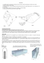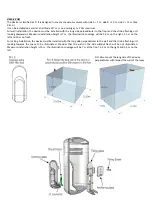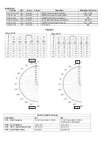
Pict. 7: connectors/terminals/trimmer
Pict. 8: END‐OF‐LINE connection in case of 2 sound
Pict.10: Connection with negative control in case of 2 sounds
CONNECTION NOT COMPLIANT TO EN54
Pict. 9: Series connection of more sounders and 2
sounds
VOLUME and ABSORBED CURRENT adjustment: Rotate trimmer P1 to adjust acoustic power
CHART 3: terminals connection
TERMINAL
Connection
S1 (1,2 and 3,4)
trigger for: sound 1 – sound 4
S2 (5 and 6)
trigger for: sound 2 – sound 5
SYNC (7)
Devices synchronism: panels and DSE3‐23 sirens. Connect to the other SYNC or B terminals
S3 (8 and 9)
trigger for: sound 3 – sound 6
CHART 2: DIP 3 – DIP 4, selection of alarm sound duration
DIP3
DIP4
Acoustic alarm duration
OFF
OFF
INFINITE (DEFAULT, COMPLYING TO EN54‐3)
ON
OFF
3 MINUTES (NOT COMPLYING TO EN54‐3)
OFF
ON
8 MINUTES (NOT COMPLYING TO EN54‐3)
ON
ON
15 MINUTES (NOT COMPLYING TO EN54‐3)
STROBE flashing device
connector
Terminal block
Trimmer for
volume adjustment
DIP‐switches
Speaker
connector
ALARM
0V
+24V
=>
=>
CONTROL
PANEL
STAND
BY
ALARM
+24V
0V
0V
+24V
EOL
EOL
CONTROL
PANEL
SND1
SND2
+24V
I = 200mA
I = 200mA
+
-
SND1
SND2
-
+


