background image


R7426D UNIVERSAL INPUT CONTROLLER


9

EN1B-0204GE51 R0403


OPERATING OVERVIEW


Display and Operation Elements


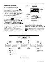
The MicroniK 200 user interface is described in Fig. 4


Note: Pushing the 

+

 or

 -

 button increments/decrements

values or scrolls through the parameter list:

  pushing one time:

single step

  pushing without release:  automatically inc./dec. or scroll

  after 3 sec pushing without release: fast automatically

inc./dec. or scroll


Changing Operating Modes


Fig. 5 shows the six operating modes. After power-up the

controller version is displayed and the controller enters the

standard display mode (Fig. 6). In this mode selected input or

output values are displayed. The controller mode is

permanently displayed by a corresponding icon (Fig. 4).


Pushing the 

+

 and

 -

 button simultaneously for approximately

1 sec the controller leaves the standard display mode and

enters the parameter/configuration selection mode (Fig. 7).

This mode is used for application configuration and to select

parameters for adjustment.


Pushing the 

SET

 button the controller accepts the selected

parameter or configuration no. and enters the adjustment

mode (Fig. 8), which is used to adjust

configuration/parameter values. After adjustment the

controller returns to selection mode by pushing the 

SET

 or

SEL

 button. Pushing the 

SEL

 button leads back to standard

display mode.


Pushing the 

SET

 and

 SEL

 button simultaneously for

approximately 1 sec the controller leaves the standard

display mode and enters the output data selection mode (Fig.

9).


Pushing the 

SET

 button enters the output adjustment mode

(Fig. 10). This mode is used for manual override of the output

value. The return to standard display mode is shown in

Fig. 5.


SET

Display

Controller Mode

Engineering 

Units

Off

Value

Push Buttons

Adjustment or

Selection

On

SEL

Selection or

Escape

Parameter/Value

Corfirmation


Fig. 4. User Interface


SET

Standard

 Display  Mode

Parameter/Config.

Selection Mode

Parameter/Config.

Adjustment Mode

and

Power up

Output

 Select ion Mode

Output 

 Adjustment Mode

Release of 
Output Fixing

no 
Output Fixing

Output Fixing

no Parameter
Value Change

Version:

R7426D 

SET

SET

SET

SET

SET

and

and

for approx.
1 sec

for approx.
1 sec

and

and

Automatic

Display

SEL

SEL

SEL

SEL

SEL


Fig. 5. Operating Overview

see Fig. 6

see Fig. 9

see Fig. 7

see Fig. 8

see Fig. 10

Содержание MicroniK 200 R7426D

Страница 1: ...y separated from the main power supply relays or other equipment which can possibly generate electromagnetic inter ference Verify that the ambient temperature and the humidity at the controller will be within the limits of 0 50 C 32 122 F and 5 to 95 rh Use shielded wiring in areas with high EMI All wiring should be separated from power lines by at least 150mm 6 Do not install controllers near fre...

Страница 2: ...ac and controller 24Vac 2 Connect line power conductors to transformer primary Line power must be supplied from a breaker panel with dedicated controller circuit Do not turn the line power on until all wiring has been checked against job drawings 3 Connect transformers 24Vac secondary to the controller terminals 18 and 19 Connect one conductor to terminal marked 24V and the other to terminal marke...

Страница 3: ...n type determines whether the limit function is low or high 1 0 1 Low limit High limit C 14 Senstyp Sensor type determines automatic detection or manual selection of NTC sensor type 0 0 1 Auto detection T3 NTC sensor type T3 C 15 Y1CTRF Control function 1 0 1 Direct control behaviour Reverse control behaviour C 22 Adr 1 Sets the serial communication address used for service or maintenance 254 0 25...

Страница 4: ...2 Throttling range cascade or limit control loop for X2 1 50 10 0 5 P 12 tr1 1 Reset time main control loop Off 20sec 20min Off 10 0 5 sec min P 13 tr2 1 Reset time cascade control loop Off 20sec 20min Off 10 0 5 sec min P 15 Ystart Start point for mid range shift of output Y1 50 50 0 0 5 P 17 X1Cal Calibration of input X1 20 20 0 0 1 P 18 X2Cal Calibration of input X2 20 20 0 0 1 P 19 T3Cal Calib...

Страница 5: ...utomatic identification of sensor type Temperature range Characteristics Pt 1000 30 130 C 1000Ω at 0 C BALCO 500 30 130 C 500Ω at 23 3 C NTC 20kΩ 30 85 C 30 130 C 1 20kΩ at 25 C 1 NTC sensor is detected automatically if during power up the sensor temperature is within 30 85 C and Senstyp 0 NTC sensor is selected manually if Senstyp is set to 1 Table 5 Sensor Types Automatic identification of senso...

Страница 6: ...nt CTRP1 the submaster setpoint Wcas is automatically altered CTRP2 Cascade control is disabled if the submaster setpoint Wcas is set to Off Low limit of CTRP2 is performed if control parameter LimTyp 0 and high limit of CTRP2 is performed if control parameter LimTyp 1 Reset Span Adjustment Rcas P 07 The reset span adjustment Rcas determines the reset effect in the submaster setpoint Wcas is alter...

Страница 7: ...ime Tu in discharge air control is normally in the range of 0 1 to 0 6min which allows adjustments of the reset time tr in a range of 0 2 to 2min In room control the response time Tu is in the range of 0 5 to 5min which results in a setting of 1 to 15min Derivative Decay Time td and Amplification vd P 27 P 28 The Proportional Integral Derivative P I D control adds the derivative function to P I co...

Страница 8: ...defines the start point of summer or winter compensation Above the compensation changeover point Wcomp summer compensation and below Wcomp winter compensation is performed Summer Winter Compensation Authority Su Wi P 04 P 05 These authority settings determine the reset effect TComp of the compensation sensor T3 on the main setpoint W1 in percentages To calculate winter and summer authority for e g...

Страница 9: ...e selected parameter or configuration no and enters the adjustment mode Fig 8 which is used to adjust configuration parameter values After adjustment the controller returns to selection mode by pushing the SET or SEL button Pushing the SEL button leads back to standard display mode Pushing the SET and SEL button simultaneously for approximately 1 sec the controller leaves the standard display mode...

Страница 10: ...six actual values can be selected and displayed Fig 6 by pushing the SEL button The icons of the permanently displayed controller mode are described in the following table Controller Mode Status Display Off Off icon On Sun icon A A Main Input X1 Main Setpoint CTRP1 Limitation Cascade Input X2 Submaster Limit Setpoint CTRP2 Compensation Temperature T3 Output Y1 SEL SEL SEL SEL SEL SEL Fig 6 Standar...

Страница 11: ...r decrements the value of the selected parameter Parameter ranges are shown in Table 3 and Table 4 An adjustment example is shown in Fig 12 Pushing the SEL button retains the old parameter value Pushing the SET button accepts the parameter value and returns to parameter configuration selection mode Resetting Parameter Values to Default Values Pushing simultaneously the or button during the power u...

Страница 12: ...he nominal control range as shown in Fig 6 To return to output selection mode three options are available Pushing the SET button after adjustment activates the manual override fixing of output value Pushing the SEL button causes that the output value is still determined by the control loop no fixing To release the manual override fixed of the output enter output adjustment mode and push the and bu...

Страница 13: ... or 1 CPA value 0 for CPATYP 2 SPA value control parameter W1 Standard Display and and and Main Sensor X1 is defective Limitation or Cascade Sensor X2 is defective Compensation Temperature Sensor T3 is defective T3 is displayed in X1 and X2 is displayed in Display if during power up no sensor is connected Display after error identification during operation Standard Display SEL SEL SEL SEL Fig 11 E...

Страница 14: ...ntrol Solutions Honeywell AG Böblinger Straße 17 D 71101 Schönaich Phone 49 7031 63701 Fax 49 7031 637493 http europe hbc honeywell com Subject to change without notice Printed in Germany Manufacturing location certified to 7157 585 EN1B 0204GE51 R0403 ...

Отзывы: