background image

Package Includes:

•  T6 Pro Thermostat

•  UWP Mounting System

•  Honeywell Standard Installation 

Adapter (J-box adapter) 

•  Honeywell Decorative Cover Plate – 

Small; size 4-49/64 in x 4-49/64 in x 

11/32 in (121 mm x 121 mm x 9 mm)

•  Screws and anchors

•  2 AA Batteries

•  Installation Instructions and User 

Guide

T6 Pro

Programmable Thermostat

Installation Instructions

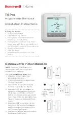
Optional Cover Plate installation

NOTE: 

If Optional Cover Plate is not 

required, see “UWP Mounting System 
installation” on next page.

Use the 

Optional Cover Plate


when: 

•  Mounting the thermostat to an 

electrical junction box

•  Or when you need to cover paint gap 

from old thermostat.

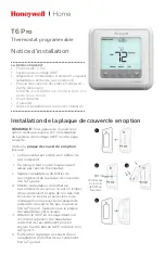
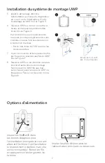
1.  Separate the Junction Box Adapter 

from the Cover Plate. See Figure 1.

2.  Mount the Junction Box Adapter to 

the wall or an electrical box using any 
of the eight screw holes. Insert and 
tighten mounting screws supplied with 
Cover Plate Kit. Do not overtighten. See 
Figure 2. Make sure the Adapter Plate 
is level. 

3.  Attach the UWP by hanging it on the 

top hook of the Junction Box Adapter 
and then snapping the bottom of the 
UWP in place. See Figure 3.

4.  Snap the Cover Plate onto the Junction 

Box Adapter. See Figure 4.

Use 2x 

supplied 

screws #6 

5/8”

4

3

2

1

Содержание Lyric T6 Pro Wi-Fi

Страница 1: ... next page Use the Optional Cover Plate when Mounting the thermostat to an electrical junction box Or when you need to cover paint gap from old thermostat 1 Separate the Junction Box Adapter from the Cover Plate See Figure 1 2 Mount the Junction Box Adapter to the wall or an electrical box using any of the eight screw holes Insert and tighten mounting screws supplied with Cover Plate Kit Do not ov...

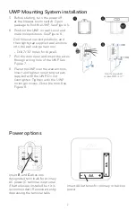
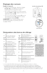
Страница 2: ...ting turn the power off at the breaker box or switch Open package to find the UWP See Figure 5 6 Position the UWP on wall Level and mark hole positions See Figure 6 Drill holes at marked positions and then lightly tap supplied wall anchors into the wall using a hammer Drill 7 32 holes for drywall 7 Pull the door open and insert the wires through wiring hole of the UWP See Figure 7 8 Place the UWP ...

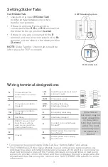
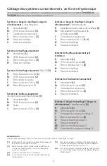
Страница 3: ...der Tabs above The THP9045A1023 Wire Saver Module is used on heat cool systems when you only have four wires at the thermostat and you need a fifth wire for a common wire Use the K terminal in place of the Y and G terminals on conventional or heat pump systems to provide control of the fan and the compressor through a single wire the unused wire then becomes your common wire See THP9045 instructio...

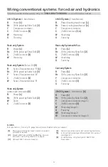
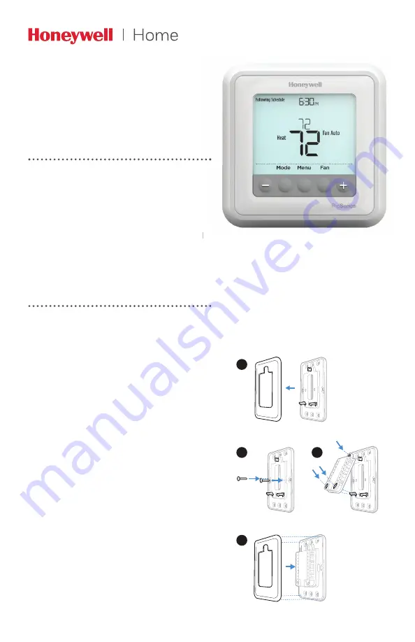
Страница 4: ... G Fan relay Cool only System R Power 1 Rc R Rc joined by Slider Tab 2 Y Compressor contactor C 24VAC common 3 G Fan relay 2H 2C System 1 transformer 6 R Power 1 Rc R Rc joined by Slider Tab 2 Y Compressor contactor stage 1 C 24VAC common 3 W Heat relay stage 1 G Fan relay W2 Heat relay stage 2 Y2 Compressor contactor stage 2 Wiring conventional systems forced air and hydronics Shaded areas below ...

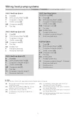
Страница 5: ...ined by Slider Tab 2 Y Compressor contactor stage 1 C 24VAC common 3 O B Changeover valve 7 G Fan relay Aux Auxiliary heat E Emergency heat relay Y2 Compressor contactor stage 2 if needed L Heat pump fault input S Outdoor sensor S Outdoor sensor Wiring heat pump systems Shaded areas below apply only to TH6320U TH6220U or as otherwise noted NOTES Wire specifications Use 18 to 22 gauge thermostat wi...

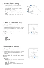
Страница 6: ...e time Thermostat mounting 1 Push excess wire back into the wall opening 2 Close the UWP door It should remain closed without bulging 3 Align the UWP with the thermostat and push gently until the thermostat snaps in place 4 Turn the power on at the breaker box or switch System operation settings 1 Press the Mode button to cycle to the next available System mode 2 Cycle through the modes until the ...

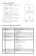
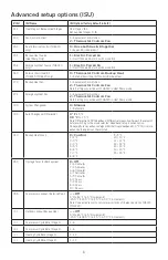
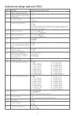
Страница 7: ...settings not all options may be available ISU ISU Name ISU Options factory default in bold 120 Scheduling Options 0 Non Programmable 2 5 2 Programmable 3 5 1 1 Programmable 4 7 Day Programmable 125 Temperature Indication Scale 0 Fahrenheit 1 Celsius 130 Outdoor Sensor TH6320 TH6220 only 0 None 1 Wired Outdoor Sensor 200 Heating System Type 1 Conventional Forced Air Heat 2 Heat Pump 3 Radiant Heat ...

Страница 8: ...r 0 Manual 1 Automatic 303 Auto Changeover Differential 0 F to 5 F 0 0 C to 2 5 C Note Differential is NOT deadband Differential means how far past the setpoint before switching to the mode selected Deadband setup is not an option Honeywell uses an advanced algorithm that fixes deadband at 0 F This is more advanced than previous thermostats 340 Backup Heat Droop 0 Comfort 2 2 F 3 3 F 4 4 F 5 5 F 6...

Страница 9: ...acement Reminder 0 Off 1 10 Run Time Days 2 20 Run Time Days 3 30 Run Time Days 4 45 Run Time Days 5 60 Run Time Days 6 90 Run Time Days 7 120 Run Time Days 8 150 Run Time Days 9 30 Calendar Days 10 45 Calendar Days 11 60 Calendar Days 12 75 Calendar Days 13 3 Calendar Months 14 4 Calendar Months 15 5 Calendar Months 16 6 Calendar Months 17 9 Calendar Months 18 12 Calendar Months 19 15 Calendar Mo...

Страница 10: ...r thermostat version information Press Select 4 Press to turn stages on one at a time and press to turn them off 5 Use the Home button to exit the System Test System test System status Shaded areas below apply only to TH6320U TH6220U or as otherwise noted Heat 0 All Off 1 Heat Stage 1 on 2 Heat Stage 2 also on 3 Heat Stage 3 also on Cool 0 All Off 1 Cool Stage 1 on 2 Cool Stage 2 also on Em Heat 0...

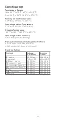
Страница 11: ...5 to 90 non condensing Physical Dimensions in inches mm H x W x D 4 1 16 H x 4 1 16 W x 1 5 32 D 103 5 mm H x 103 5 mm W x 29 mm D Electrical Ratings Terminal Voltage 50 60Hz Running Current W Heating 20 30 Vac 0 02 1 0 A Powerpile 750 mV DC 100 mA DC W2 Aux Heating 20 30 Vac 0 02 1 0 A E Emergency Heat 20 30 Vac 0 02 0 5 A Y Compressor Stage 1 20 30 Vac 0 02 1 0 A Y2 Compressor Stage 2 20 30 Vac ...

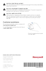
Страница 12: ...2 Customer assistance Pull to remove the thermostat from the UWP CAUTION MERCURY NOTICE If this product is replacing a control that contains mercury in a sealed tube do not place the old control in the trash Contact your local waste management authority for instructions regarding recycling and proper disposal CAUTION EQUIPMENT DAMAGE HAZARD Compressor protection is bypassed during testing To preve...

Страница 13: ... il faut couvrir l espace peint laissé par l ancien thermostat 1 Séparer l adaptateur du boîtier de raccordement de la plaque de couvercle Voir la Figure 1 2 Monter l adaptateur du boîtier de raccordement sur le mur ou sur un boîtier de raccordement à l aide de l un des huit trous de vis Insérer et serrer les vis de montage fournies avec le nécessaire de plaque de couvercle Ne pas trop serrer Voir...

Страница 14: ...ndre l alimentation au niveau du disjoncteur du circuit ou de l interrupteur Ouvrir l emballage du UWP Voir la Figure 5 6 Placer le UWP sur le mur Le mettre à niveau et marquer les positions des trous Voir la Figure 6 Percer des trous aux emplacements marqués puis taper légèrement sur les chevilles murales fournies dans le mur à l aide d un marteau Percer des trous de 7 32 po pour les cloisons sèc...

Страница 15: ...ne peut être reliée à l aide du curseur Voir Réglage des curseurs ci dessus Le module économiseur de fils THP9045A1023 est utilisé sur les systèmes de chauffage refroidissement lorsque vous n avez que quatre fils sur le thermostat et qu un cinquième fil est nécessaire comme fil commun Utilisez la borne K à la place des bornes Y et G sur les systèmes conventionnels ou à thermopompe pour assurer le ...

Страница 16: ...niquement R Alimentation 1 Rc R Rc liés par le curseur 2 Y Contacteur du compresseur C Borne commune 24 V c a 3 G Relais de ventilateur Système à 2 étages de chauffage 2 étages de refroidissement 1 transformateur 6 R Alimentation 1 Rc R Rc liés par le curseur 2 Y Contacteur de compresseur étage 1 C Borne commune 24 V c a 3 W Relais de chauffage étage 1 G Relais de ventilateur W2 Relais de chauffag...

Страница 17: ...r de compresseur étage 1 C Borne commune 24 V c a 3 O B Vanne de commutation 7 G Relais de ventilateur Aux Chauffage auxiliaire E Relais de chauffage d urgence Y2 Contacteur de compresseur étage 2 au besoin L Entrée de faute de thermopompe S Capteur extérieur S Capteur extérieur Câblage des systèmes à thermopompe Les zones ombrées ci dessous s appliquent uniquement aux modèles TH6320U TH6220U ou e...

Страница 18: ...ps Montage du thermostat 1 Repousser le fil en excès dans l ouverture du mur 2 Fermer le couvercle du UWP Elle doit rester fermée sans renflement 3 Aligner l UWP sur le thermostat et appuyer doucement jusqu à ce que le thermostat s enclenche en place 4 Mettre l alimentation en marche au niveau du disjoncteur du circuit ou de l interrupteur Réglages pour le fonctionnement du système 1 Appuyer sur l...

Страница 19: ...U REMARQUE En fonction des paramètres du système ces options peuvent ne pas être toutes disponibles N ISU Nom ISU Options ISU réglage d usine en gras 120 Options de programmation 0 Non programmable 2 5 2 programmable 3 5 1 1 programmable 4 7 jours programmable 125 Échelle d indication de température 0 Fahrenheit 1 Celsius 130 Capteur d extérieur TH6320 TH6220 uniquement 0 Aucun 1 Capteur extérieur...

Страница 20: ...C Remarque Le différentiel n est PAS la zone morte Le différentiel représente la valeur supérieure au point de consigne avant le passage au mode sélectionné Le réglage de la zone morte n est pas une option Honeywell utilise un algorithme de pointe qui définit la zone morte à 0 F Ce réglage est supérieur aux thermostats précédents 340 Variation de charge du chauffage de secours 0 Confort 2 2 F 3 3 ...

Страница 21: ... 4 45 jours de fonctionnement 5 60 jours de fonctionnement 6 90 jours de fonctionnement 7 120 jours de fonctionnement 8 150 jours de fonctionnement 9 30 jours calendaires 10 45 jours calendaires 11 60 jours calendaires 12 75 jours calendaires 13 3 mois calendaires 14 4 mois calendaires 15 5 mois calendaires 16 6 mois calendaires 17 9 mois calendaires 18 12 mois calendaires 19 15 mois calendaires 7...

Страница 22: ...tionner 4 Appuyer sur pour activer les étages un à la fois et appuyer pour les désactiver 5 Utiliser le bouton Home Accueil pour quitter le test du système Test du système Statut du système Les zones ombrées ci dessous s appliquent uniquement aux modèles TH6320U TH6220U ou en cas d indication contraire Chauffage 0 Tous désactivés 1 Chauffage étage 1 activé 2 Chauffage étage 2 également activé 3 Ch...

Страница 23: ...H x L x P 4 1 16 po de haut x 4 1 16 po de large x 1 5 32 po de profondeur 103 5 mm de haut x 103 5 mm de large x 29 mm de profondeur Caractéristiques électriques Borne Tension 50 60 Hz Courant de fonctionnement W Chauffage 20 30 V c a 0 02 1 0 A Powerpile 750 mV c c 100 mA c c W2 Aux Chauffage 20 30 V c a 0 02 1 0 A E Chauffage d urgence 20 30 V c a 0 02 0 5 A Y Étage de compresseur 20 30 V c a 0...

Страница 24: ...er pour retirer le thermostat du UWP MISE EN GARDE AVIS RELATIF AU MERCURE Si ce produit remplace un régulateur contenant du mercure dans un tube scellé ne pas mettre l ancien régulateur à la poubelle Contacter le responsable de gestion des déchets local pour les instructions concernant le recyclage et l élimination MISE EN GARDE RISQUE DE DOMMAGES DE L ÉQUIPEMENT La protection du compresseur est ...

Страница 25: ...lmes eléctricos O cuando necesite cubrir un espacio de pintura que haya dejado el termostato existente 1 Separe el adaptador del cajetín de empalmes de la placa de cubierta Consulte la Figura 1 2 Monte el adaptador del cajetín de empalmes a la pared o a un cajetín eléctrico utilizando cualquiera de los ocho agujeros para los tornillos Inserte y apriete los tornillos de montaje que se suministran c...

Страница 26: ...icidad en la caja de interruptores de circuito o el interruptor Abra el paquete para encontrar la UWP Consulte la Figura 1 6 Coloque la UWP en la pared Nivele y marque la posición de los tornillos Consulte la Figura 2 Perfore agujeros en las posiciones marcadas y después introduzca en la pared los tarugos que se suministran golpeando ligeramente con un martillo Perfore orificios de 7 32 5 6 mm en ...

Страница 27: ... uno o dos sistemas de transformadores Si hay solo un cable R y está conectado al terminal R Rc o RH coloque el control deslizante en la posición superior 1 cable Si hay solo un cable conectado al terminal R y un cable conectado al terminal Rc configure el control deslizante en la posición inferior 2 cables NOTA Las lengüetas de los controles deslizantes para terminales U deben dejarse en su lugar...

Страница 28: ...ntilador Sistema de refrigeración únicamente R Alimentación 1 Rc R Rc unidos por la lengüeta del control deslizante 2 Y Contactor del compresor C Común de 24 V CA 3 G Relé del ventilador Sistema de 2 etapas de calefacción 2 etapas de refrigeración 1 transformador 6 R Alimentación 1 Rc R Rc unidos por la lengüeta del control deslizante 2 Y Contactor del compresor etapa 1 C Común de 24 V CA 3 W Relé...

Страница 29: ...mentación 1 Rc R Rc unidos por la lengüeta del control deslizante 2 Y Contactor del compresor etapa 1 C Común de 24 V CA 3 O B Válvula de cambio 7 G Relé del ventilador Aux Calefacción auxiliar E Relé de calefacción de emergencia Y2 Contactor del compresor etapa 2 si fuese necesario L Entrada de detección de falla de la bomba de calor S Sensor exterior S Sensor exterior Cableado de sistemas de bom...

Страница 30: ...mpo Montaje del termostato 1 Introduzca el excedente de cable en la abertura de la pared 2 Cierre la tapa de la placa de la UWP Debe permanecer cerrada sin quedar protuberante 3 Alinee la UWP con el termostato y presione suavemente hasta que el termostato calce en su lugar 4 Conecte el suministro de electricidad en la caja de interruptores de circuito o en el interruptor Configuraciones del sistem...

Страница 31: ...pcionesdelISU lasconfiguracionespredeterminadasdefábricaestánennegrita 120 Opciones de programación 0 No programable 2 Programable 5 2 3 Programable 5 1 1 4 Programable para 7 días 125 Escala de indicación de temperatura 0 Fahrenheit 1 Centígrados 130 Sensor exterior TH6320 TH6220 únicamente 0 Ninguno 1 Sensor exterior cableado 200 Tipo de sistema de calefacción 1 Calefacción de aire forzado conve...

Страница 32: ... diferencial NO es la banda muerta El diferencial significa cuánto avanza después de pasar el punto de referencia antes de cambiar al modo seleccionado La configuración de la banda muerta no es una opción Honeywell utiliza un algoritmo avanzado que fija la banda muerta en 0 ºF Esto es más avanzado que en los termostatos anteriores 340 Descenso del calor de reserva 0 Confort 2 2 F 3 3 F 4 4 F 5 5 F...

Страница 33: ...e ejecución 4 45 días de tiempo de ejecución 5 60 días de tiempo de ejecución 6 90 días de tiempo de ejecución 7 120 días de tiempo de ejecución 8 150 días de tiempo de ejecución 9 30 días calendario 10 45 días calendario 11 60 días calendario 12 75 días calendario 13 3 meses calendario 14 4 meses calendario 15 5 meses calendario 16 6 meses calendario 17 9 meses calendario 18 12 meses calendario 1...

Страница 34: ...resione Select seleccionar 4 Presione para activar las etapas una a la vez y vuelva a presionar para desactivarlas 5 Use el botón Home inicio para salir de la prueba del sistema Prueba del sistema Estados del sistema Las áreas sombreadas siguientes se aplican únicamente a TH6320U TH6220U o según se indique Calefacción 0 Todo apagado 1 Etapa de calefacción 1 activada 2 Etapa de calefacción 2 tambié...

Страница 35: ...imensiones físicas en pulgadas mm alto x ancho x profundidad 4 1 16 H x 4 1 16 W x 1 5 32 D 103 5 mm de alto x 103 5 mm de ancho x 29 mm de profundidad Clasificaciones eléctricas Terminal Voltaje 50 60Hz Corriente de funcionamiento W Calefacción 20 30 V CA 0 02 1 0 A Powerpile 750 mV CC 100 mA CC W2 Calefacción Aux 20 30 V CA 0 02 1 0 A E Calefacción de emergencia 20 30 V CA 0 02 0 5 A Y Etapa 1 d...

Страница 36: ...e la UWP PRECAUCIÓN AVISO SOBRE EL MERCURIO Si este producto está reemplazando a un equipo de control existente que contiene mercurio en un tubo sellado no coloque dicho equipo en la basura Contacte al organismo encargado del manejo y disposición de desechos de su localidad para obtener instrucciones sobre cómo reciclar y desechar adecuadamente PRECAUCIÓN RIESGOS DE DAÑOS AL EQUIPO Se evita la pro...

Отзывы: