HONEYWELL CONFIDENTIAL
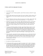
TX Driver and TX Final Alignment Procedures:
1.
Set the IFR to ATCRBS.
2.
Verify that R1 on the TX Final board and R3 on the TX Driver board are set fully CCW. Apply
unit power.
3.
On the TX Driver board, measure the voltage at L4 (scope or voltmeter). Set this voltage to 4.5V
by adjusting R3 CW. Note that the total unit current draw at this time should be no more than
190ma.
4.
On the TX Final board, attach scope probe to the junction of L11 and R16. Adjust R1 CW while
observing a positive pulse on the scope. Set this pulse height to 3.8 V (maximum is 4 V).
5.
Adjust the scope to observe the 1st TX pulse. While observing this 1st pulse, on the TX Final
board, start by adjusting C27 first, then C44 and then C26 (in this order) for maximum TX
pulse power as observed on the scope and IFR Power Monitor. Also, observe this pulse and
adjust the three tuning caps slightly for the best Pulse Top flatness and Rise and Fall time
linearity.
6.
Check the pulse Width measurement. It should be approximately 430nsec at this time. If not,
on the TX Driver board, adjust R4 (first) and then R30 to set the preliminary pulse width to
430ns. The pulse Rise time should be greater than 50ns and less than 100ns. The pulse Fall
time should be greater than 50ns and less than 170ns. Make minor readjustments to C27, C44,
and C26 on the TX Final board as necessary to bring the pulse Rise and Fall times within
specifications. Check the power output on the IFR display. It should be greater than 125W
minimum.
7.
Set the scope delay to approximately 20.5usec and adjust as necessary to observe the last pulse
of the TX pulse train. Check the TX Pulse Width. It should be approximately 430nsec. If not,
make a slight adjustment to R4 then R30 on the driver board. Verify the pulse Rise and Fall
times are within the specifications listed above. If not, make minor adjustments to the TX
board tuning caps as necessary.
8.
Set the IFR to Long Mode S.
9.
Set up the scope to observe the first TX Pulse.
10.
Check the pulse width measurement. It should be a minimum of 520 +/- 10nsec. If necessary,
on the TX Driver board, adjust R4 then R30 to set this pulse width to 520nsec. The pulse Rise
time should be greater than 50ns and less than 100ns. The pulse Fall time should be greater
than 50ns and less than 170ns. Again, if necessary, make minor readjustments to C27, C44,
and C26 on the TX Final board to bring the pulse Rise and Fall times within specifications.
Check the power output on the IFR display. It should be greater than 125W minimum.
Honeywell International Inc.
001-05117-0010
KXP2290 Diversity Mode S Transponder
Revision -
Alignment Procedure
8 of 11
Содержание KXP2290
Страница 1: ......


