background image


D201002000008


Rev 1, December 2014 

© 2007, 2008, 2010, 2014 Honeywell International Inc. 


Honeywell International Inc.  
15001 N.E. 36th Street • P.O. Box 97001  
Redmond, Washington USA 98073-9701  
CAGE 97896 
E-mail: 

[email protected]


Telephone: 800-601-3099 (U.S.A.) 
Telephone: 602-365-3099 (International) 
FAX: 602-822-7272  

https://myaerospace.honeywell.com/


Содержание IntuVue RDR-4000

Страница 1: ...IntuVue RDR 4000 IntuVue 3 D Automatic Weather Radar System with Forward Looking Windshear Detection For Airbus SA LR Aircraft Pilot s Guide ...

Страница 2: ... means without the express written permission of Honeywell International Inc is prohibited For further information contact Honeywell Aerospace Technical Publications E mail cas publications distribution honeywell com Telephone 800 601 3099 U S A Telephone 602 365 3099 International Web site https myaerospace honeywell com The information contained in this manual is for reference use only If any in...

Страница 3: ...PANDED OPERATING INSTRUCTIONS 11 TURN ON SYSTEM SELECTION 11 WEATHER DETECTION 12 AUTOMATIC WEATHER MODE ALL ALL WX OR ON PATH PATH WX 12 TURBULENCE DETECTION 14 PREDICTIVE HAIL AND LIGHTNING HAZARD DISPLAY FEATURE 15 REACT HAZARD DISPLAY FEATURE 16 WX TURB AHEAD ALERTING HAZARD DISPLAY FEATURE 17 PREDICTIVE WINDSHEAR PWS DETECTION 18 WEATHER ANALYSIS 22 ELEVATION WEATHER MODE 22 FULL COVERAGE GRO...

Страница 4: ...CELL CHARACTERISTICS 38 PLANNING A PATH 40 AZIMUTH RESOLUTION 43 ANGULAR RESOLUTION EFFECT ON VERTICAL RESOLUTION 43 SHADOWED AREAS 44 EFFECTS OF INTERFERING RF SOURCES 45 RADAR WINDSHEAR DETECTION 48 WINDSHEAR MICROBURST DESCRIPTION 48 WINDSHEAR MICROBURST DETECTION PROCESS 48 WINDSHEAR AVOIDANCE FLYING 49 SECTION 6 RDR 4000 TECHNICAL OPERATION 51 3D VOLUMETRIC MEMORY SCANNING PROCESSING 51 GROUN...

Страница 5: ...Lightning Icons if installed o Areas ahead of the aircraft that have a high probability of producing hail or lightning are indicated by the display of appropriate icons REACT Rain Echo Attenuation Compensation Technique if installed o Indicates areas where attenuation of the radar signal is severe enough to degrade the ability to display weather behind significant intervening weather Automatic con...

Страница 6: ...ressed Only the weather that is relevant to the flight path is shown o In ELEVN mode view horizontal slices through the weather in 1 000 foot increments from ground level to 60 000 ft Weather Turbulence Ahead Alerting o Alerts the pilot when significant weather or turbulence is detected on the flight path trajectory Map mode for identification of terrain features o Use MAP mode for identifying pro...

Страница 7: ... detected or displayed The weather display corresponds to the selected range while the turbulence display is overlaid for the first 40 nm in the ALL and ON PATH modes regardless of range selected If the Hazard Display features are installed turbulence will be displayed for the first 60 nm and will be shown in the ALL WX PATH WX and ELEVN modes Hail and lightning icons indicate that conditions are ...

Страница 8: ...IntuVue RDR 4000 Weather Radar Pilot s Guide Introduction D201002000008 4 Rev 1 December 2014 ...

Страница 9: ...hich features are available on your system Modes OFF ALL ON PATH ELEVN MAP OFF ALL WX PATH WX ELEVN MAP Turbulence Detection First 40 nm ALL and ON PATH modes First 60 nm ALL WX PATH WX and ELEVN modes Hazard Detection Not available First 160 nm ALL WX PATH WX and ELEVN modes REACT Not available Provided in ALL WX PATH WX and ELEVN modes WX Turb Ahead Alerting Not available Alerts provided when tu...

Страница 10: ...FF Or the System Control Switch on the Radar control panel is set to either System 1 or System 2 and o The aircraft is on the ground and the PWS Qualifiers are not satisfied See AUTOMATIC WINDSHEAR ACTIVATION on pg 18 o And the Display Selection Knobs for both the CAPT and F O are set to OFF The Radar is ON Transmitting when The System Control Switch on the Radar control panel is set to either Sys...

Страница 11: ...ge 25 for more details Range Pilot Flying 10 to 40 nm other side at least one range higher Avoid any magenta turbulence cells and monitor the display for weather intensity to avoid any weather threats Avoid any cells associated with Hail or Lightning Icons see page 15 In areas where the REACT field is shown expect the possibility of weather that may need to be avoided see page 16 If there is weath...

Страница 12: ...d see page 16 See PLANNING A PATH on page 40 for more information CRUISE ABOVE FL200 System Control 1 or 2 dual system or 1 single system Turb Switch AUTO or Turb Pushbutton Engaged HZD Pushbutton if provided Engaged Mode ALL ALL WX or ON PATH PATH WX Gain AUTO or as required to assess threats Refer to GAIN CONTROL on page 25 for more details Range Pilot Flying 20 to 80 nm other side at least one ...

Страница 13: ...o GAIN CONTROL on page 25 for more details Range Pilot Flying 10 to 40 nm other side at least one range higher Avoid any magenta turbulence cells and monitor the display for weather intensity to avoid any weather threats Avoid any cells associated with Hail or Lightning Icons see page 15 In areas where the REACT field is shown expect the possibility of weather that may need to be avoided see page ...

Страница 14: ...ve activity Avoid any cells associated with Hail or Lightning Icons by a minimum of 20 nm see page 15 In areas where the REACT field is shown expect the possibility of weather that may need to be avoided see page 16 Establish an avoidance plan before getting within 40 nm of the cells to allow time to negotiate a deviation with ATC See PLANNING A PATH on page 40 for more information Consider the he...

Страница 15: ...o OFF unless the PWS qualifiers are active see AUTOMATIC WINDSHEAR ACTIVATION on pg 18 When in the air the radar scans continuously always updating the memory so that current weather is immediately available See also ON OFF on page 6 On initial activation of the radar or when switched from one system to the other 1 or 2 the radar first looks at the part of the sky that is near the aircraft s altit...

Страница 16: ... Green Light 20 30 dBZ 0 7 4 mm hr 0 028 0 16 in hr Yellow Medium 30 40 dBZ 4 12 mm hr 0 16 0 47 in hr Red Strong 40 dBZ or greater Greater than 12 mm hr 0 47 in hr Magenta Turbulence N A N A ON PATH PATH WX WEATHER The RDR 4000 fills the 3D memory with all the detected weather in front of the aircraft out to 320 nm and from ground level up to 60 000 ft mean sea level MSL The RDR 4000 displays wea...

Страница 17: ...LL ALL WX AND ON PATH PATH WX MODES In ALL ALL WX or ON PATH PATH WX mode the RDR 4000 projects a three dimensional memory space onto a two dimensional display This means the weather displayed for any one memory cell is the color of the strongest return in that column of memory cells Specifically if there is any weather data in a given column that is inside the envelope for on path weather the col...

Страница 18: ...lled Turbulence within this range and inside the turbulence envelope will be displayed in magenta The turbulence data is represented in a blocky shape helping to visually differentiate it from reflectivity data If required the display of turbulence information may be turned off by setting the Turbulence Select Switch to OFF or by disengaging the Turbulence Pushbutton The turbulence detection featu...

Страница 19: ...Range As desired The radar does not directly detect hail or lightning it analyzes the data in the 3D memory to identify areas that have a high probability of containing these hazards Hail and lightning icons indicate that conditions in the associated weather cell are conducive to the development of hail or lightning They do not guarantee that hail or lightning will be present nor does the absence ...

Страница 20: ...nfiguration of the RDR 4000 automatically indicates areas where the radar signal has been attenuated These areas are shown as magenta arcs superimposed over the reflectivity in the areas where the signal attenuation is significant These arcs indicate that there could be severe weather in that area even though only mild or no reflectivity is shown In areas where the REACT field is shown expect the ...

Страница 21: ...ut to three minutes ahead at current aircraft speed The presence of turbulence or weather threats is indicated by An advisory text message WEATHER AHEAD on the display when the aircraft altitude is more than 1 500 ft AGL and weather or turbulence hazards are detected within the corridor An aural alert Weather Ahead Weather Ahead when all of the following conditions are met o WXR is not selected fo...

Страница 22: ...SHEAR ACTIVATION The Windshear mode will automatically be turned on under the following specific aircraft conditions In Air Below 1 800 ft AGL On Ground Typically oil pressure active and either ground speed greater than 30 kts or longitudinal acceleration greater than 0 15g If the display is showing data other than weather such as ground proximity terrain data when a windshear event takes place th...

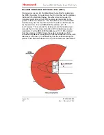
Страница 23: ...er than 100 kts on takeoff or greater than 60 kts on approach WARNING ALERTS The WARNING Alert region is 0 25 nm either side of the aircraft track and from 0 5 nm to 1 5 nm 3 0 nm on the ground in front of the aircraft On approach below 370 ft warnings beyond the far end of the runway are inhibited Between 50 ft and 1 200 ft AGL the system indicates WARNING Alerts with visual and aural annunciatio...

Страница 24: ...Weather Radar Pilot s Guide Expanded Operating Instructions D201002000008 20 Rev 1 December 2014 TAKE OFF ALERT REGIONS WINDSHEAR TAKE OFF ALERT REGIONS WINDSHEAR APPROACH ALERT REGIONS WINDSHEAR APPROACH ALERT REGIONS ...

Страница 25: ...ected VISUAL PWS ALERT ANNUNCIATIONS Visual Caution and Warning Alerts are annunciated on the Electronic Displays Caution Visual Alert Amber W S AHEAD Warning Visual Alert Red W S AHEAD AURAL PWS ALERT ANNUNCIATIONS Caution and Warning Alerts are annunciated by the cockpit audio system Caution Aural Alerts may be one of the following selected at installation Option 1 Whoop Whoop Option 2 Monitor R...

Страница 26: ...th providing a view at a constant altitude level Selecting ELEVN on the mode selection knob enters the Elevation Mode On initial selection the altitude slice is set to the current aircraft altitude nearest 1 000 ft The Elevation Selection Knob is used to select the desired altitude slice from 0 to 60 000 ft in 1 000 foot intervals Off path weather information is removed in ELEVN mode to enhance an...

Страница 27: ... purpose of the MAP mode is to aid in identifying prominent terrain features such as coastlines lakes and large built up urban areas MAP mode provides an extended ground map picture by piecing together individual scans and combining them in the memory for display Reflectivity data that is considered ground clutter and removed from the weather views is the basis for the Ground Map Data from the ter...

Страница 28: ...tuVue RDR 4000 Weather Radar Pilot s Guide Expanded Operating Instructions D201002000008 24 Rev 1 December 2014 RDR 4000 SEATTLE AREA MAP DISPLAY SEATTLE AREA SATELLITE IMAGE Picture from earth google com ...

Страница 29: ... at AUTO Color Returns Reflectivity Rainfall Rate Black Very light or none Less than 20 dBZ Less than 0 7 mm hr 0 028 in hr Green Light 20 30 dBZ 0 7 4 mm hr 0 028 0 16 in hr Yellow Medium 30 40 dBZ 4 12 mm hr 0 16 0 47 in hr Red Strong 40 dBZ or greater Greater than 12 mm hr 0 47 in hr Magenta Turbulence N A N A Rotating the GAIN Knob to the minimum MIN position reduces gain by approximately 16 d...

Страница 30: ... is apparent on the weather display See SHADOWED AREAS on page 44 Use MAX gain only when at cruise altitudes In ELEVN mode MAX gain is useful when looking at altitude slices above the freezing level where particles are less reflective High levels of moisture above the freezing level are key ingredients in hail formation Increase the gain briefly at any altitude to discover the relative reflectivit...

Страница 31: ...radar pulses used to detect turbulence windshear weather and terrain targets It also contains the system integrity monitoring and self test electronics The TR 1 is located in the radome in the base of the antenna drive DA 1A B ANTENNA DRIVE WITH FP30 1 ANTENNA The component parts of the antenna drive are the DA 1A single or DA 1B dual Antenna Drive and the FP30 1 flat plate array The antenna drive...

Страница 32: ... side display First Officer The flight crew can operate each side independently without impacting radar performance thus achieving maximum weather information display The one GAIN control knob affects both displays The control panel for installations that include the Hazard Display Features uses pushbuttons for engaging or disengaging the turbulence and hazard display features These control panels...

Страница 33: ...ystem Therefore there is no advantage in switching between systems during flight except in the case of the failure of one side The Display Selection Knob dictates which information is presented to the pilots For immediate access to the most up to date weather display leave the radar on and turn the Display Selection Knob to OFF if you do not want to see the WXR information on your display When it ...

Страница 34: ... the feature is active AUTO Turbulence indications will be overlaid on the weather display in ALL and ON PATH modes OFF Turbulence data will not be shown ENGAGED Turbulence indications will be overlaid on the weather display in ALL WX PATH WX and ELEVN modes HAZARD DISPLAY CONTROL Push the HZD button to engage Push it again to disengage the feature A light will indicate when the feature is active ...

Страница 35: ...o 5 nm turbulence out to 40 nm and weather out to 320 nm ON PATH or PATH WX Automatic Weather Mode Only On Path weather is shown Off Path weather is suppressed This mode provides display of windshear out to 5 nm turbulence out to 40 nm or 60 nm for PATH WX and weather out to 320 nm ELEVN Constant Elevation Weather Analysis Mode Only weather at the selected elevation is shown The elevation slice de...

Страница 36: ...tting is QFE QNH the elevation of the weather slice will be given in thousands of ft KFT GAIN CONTROL AUTO Rotate to the AUTO position for automatic gain control The AUTO position results in a calibrated map or weather radar display Gain control does not affect turbulence or windshear Manual Rotating the knob out of AUTO varies the gain between MIN and MAX MAN GAIN is shown on the display indicati...

Страница 37: ...lay dependent The following figure is provided as an example only WEATHER RADAR DISPLAY ANNUNCIATIONS EXAMPLE G GA AI IN N W WX XR R M MO OD DE E E EL LE EV VA AT TI IO ON N F FA AU UL LT T Gain MAN GAIN Or blank Mode WX ALL PATH WX ELEVN MAP PWS SCAN Elevation XX000 FT or FL XXX Or TURB OFF Or blank Fault WXR R T WXR RNG WXR CTL WXR ANT PRED W S Or blank ...

Страница 38: ... system If a system failure occurs a generic WXR FAIL message will be annunciated on the display Failures will appear as red caution annunciations on the display Some faults will cause any displayed radar data to disappear entirely If the fault does not resolve itself shortly try cycling power to the system In a dual installation select the other system If none of these actions correct the problem...

Страница 39: ...unciations Display Annunciation Failure WXR R T Radar Processor RP 1 or Transmitter Receiver TR 1 Unit Failure WXR ANT Antenna Drive Failure WXR CTL Control Panel Fault WXR RNG Display Fault PRED W S Predictive Windshear Inop See the aircraft installation documentation for complete descriptions of the possible failure modes ...

Страница 40: ...IntuVue RDR 4000 Weather Radar Pilot s Guide Equipment Description D201002000008 36 Rev 1 December 2014 ...

Страница 41: ...tween the storms and maintain visual separation from them Weather radar detects droplets of precipitation size The strength of the radar return echo depends on drop size composition and amount of water Water particles return almost five times as much signal as ice particles of the same size This means that rain is more easily detected than snow although at times large wet snowflakes may give a str...

Страница 42: ...ion results in towering storm structures that can contain high wind gradients that lead to turbulent motion Very vigorous convection can generate severe turbulence near the high reflectivity core downwind of the core and at the top of the storm The strength of the convection can be judged by the vertical size of the convective cell and the extent of high reflectivity portions of the storm The RDR ...

Страница 43: ...n rates as well as from enhancement of reflectivity due to melting of snow particles just below the freezing level High reflectivity of stratus weather does not indicate any significant hazard with the exception of any potential for icing or takeoff and landing performance issues associated with high rainfall rates ICING Updrafts in thunderstorms support abundant water when carried above the freez...

Страница 44: ...cloud and hazardous turbulence may extend as much as 20 nm from the cloud You should avoid the most intense echoes by at least 20 nm if possible If the Hazard Display features are installed avoid areas with hail or lightning icons by a similar distance As echoes diminish in intensity you can reduce the distance by which you avoid them The lightning and hail icons provide additional clues as to whe...

Страница 45: ...e hazard o Icons are generally placed on the display at or near the center of the area where the hazard producing convection is located It is possible that a single icon could indicate the presence of a number of separate hazardous convective cells in order to avoid display clutter To better resolve the individual convective cells with hazards associated select a lower display range It is possible...

Страница 46: ...staying upwind of the most severe hazards In areas where the REACT field is shown expect the possibility of additional weather that may need to be avoided When REACT fields are shown the geometry between the aircraft and the attenuating weather may change as the flight progresses This may allow weather that was in the REACT area to later be outside of the REACT field and the radar will then more c...

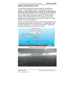
Страница 47: ... also results in storm cells that will tend to appear to be wider in azimuth than the actual width The increase in apparent azimuth width increases with increasing range ANGULAR RESOLUTION EFFECT ON VERTICAL RESOLUTION Beam width also has a range dependent effect on the vertical resolution of weather The typical effect is to cause the apparent echo tops of the weather to be increasingly higher in ...

Страница 48: ... behind the strong weather echo With very heavy intervening rain the ground returns behind the echo will not be present but rather will appear as a shadow This may indicate a larger area of precipitation than appears on the weather display Corresponding MAP display The lack of radar returns in the circled areas indicates that terrain or very heavy rain in front of those areas prevents the radar si...

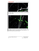
Страница 49: ...Algorithms in the software suppress most of these returns but they cannot always be completely suppressed Once the source of interference is no longer active the spots will typically be removed after the antenna re scans the area and updates the memory approximately thirty seconds Adjusting the manual gain may help alleviate the effect of the interfering source but the effect will not completely d...

Страница 50: ... Rev 1 December 2014 This figure shows a zoomed in view of the near range interference from the previous figure In this figure the interference is a bit more subtle as it is mixed in with real weather However a close look reveals several radial spokes The two most obvious ones have been circled ...

Страница 51: ...IntuVue RDR 4000 Weather Radar Pilot s Guide D201002000008 Principles of Weather Radar Use Rev 1 December 2014 47 These figures show more examples of RF interference ...

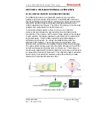
Страница 52: ...aft s wind characteristics are identical When the downward moving airflow becomes a horizontal flow at the base of the airshaft the outflow winds have front to back velocities ranging from 20 to 80 knots WINDSHEAR MICROBURST DETECTION PROCESS When the airshaft of a microburst encounters the ground it mushrooms outward By measuring the horizontal velocity of the associated water droplets the RDR 40...

Страница 53: ...d by the wing is related to the relative velocity of air traveling over the wing If the air velocity suddenly changes so does the lift When the lift is reduced the aircraft descends As an aircraft enters a microburst depending on the point of entry it will experience at least one of these conditions and most probably both The key to surviving a microburst is to enter it at a high enough aircraft e...

Страница 54: ...IntuVue RDR 4000 Weather Radar Pilot s Guide Technical Operation D201002000008 50 Rev 1 December 2014 ...

Страница 55: ...the approximately 4 second side to side movements of the antenna and the radar image update on the displays In such systems the display update is synchronized to the antenna tilt angle and sweep Only the data needed for immediate display is collected and processed In contrast the RDR 4000 system has eliminated this limitation The mechanical scanning pattern of the antenna is de coupled from the we...

Страница 56: ... curvature of the earth Horizontal views are generated independently for each side of the cockpit GROUND CLUTTER EXTRACTION The radar processor contains an internal terrain database with elevation data The radar compares the collected reflectivity data with the terrain database Reflectivity data that correlates to terrain data is considered ground clutter and is suppressed from the weather images ...

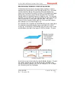
Страница 57: ...tegic detection of weather This fully automatic weather detection is enabled by the 3D volumetric memory In these modes on path weather or weather near the altitude of the intended flight path is displayed as distinct from off path weather which is further removed in altitude from the flight path The result is a presentation of weather information that is intuitive improves awareness of the entire...

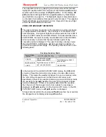
Страница 58: ...vective cells are displayed The upper boundary cannot go lower than 10 000 ft MSL Additionally absolute envelope boundaries of 60 000 ft and ground level apply The resulting rules are shown in the following table Envelope boundary limits Aircraft Altitude ft MSL Lower Envelope Boundary Upper Envelope Boundary 29 000 25 000 ft MSL or Flight Altitude minus 4000 ft 29 000 to 6 000 Flight Altitude plu...

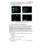
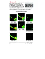
Страница 59: ...on view provides a plan view that represents a thin slice through the volumetric memory of weather reflectivity data This view is corrected for the curvature of the earth i e it is a view at a constant MSL altitude level or constant Flight Level The elevation slice is selected by the ELEVN knob on the control panel The elevation is selectable between zero and 60 000 ft in 1 000 ft increments On ac...

Страница 60: ...s been selected so this is an elevation slice at the current aircraft altitude 20 000 ft MSL The remaining pictures show the returns at different elevations Observe that the cell tops exceed 25 000 ft CONSTANT ELEVATION MODE EXAMPLE USING VARYING ELEVATIONS ALL ALL WX MODE ELEVATION MODE SLICE AT 20 000FT e g AT A C ALTITUDE ELEVATION MODE SLICE AT 15 000 FT ELEVN MODE SLICE AT 10 000 FT ELEVN MOD...

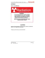
Страница 61: ...er Radar Pilot s Guide D201002000008 Appendix Rev 1 December 2014 57 APPENDIX SAFETY INFORMATION CAUTION MAINTAIN PRESCRIBED SAFE DISTANCE WHEN STANDING IN FRONT OF A RADIATING ANTENNA Reference FAA Advisory Circular 20 68B ...

Страница 62: ...e first distance is the near field far field boundary which is the distance from the antenna that it takes for the beam to form For the RDR 4000 this distance is 14 ft 4 27 meters The second is the distance where the radiation level exceeds the U S Government standard of 10 milliwatts per square centimeter For the RDR 4000 this distance is 11 8 ft 3 58 meters from the antenna In TEST mode the syst...

Страница 63: ......

Страница 64: ... Inc Honeywell International Inc 15001 N E 36th Street P O Box 97001 Redmond Washington USA 98073 9701 CAGE 97896 E mail cas publications distribution honeywell com Telephone 800 601 3099 U S A Telephone 602 365 3099 International FAX 602 822 7272 https myaerospace honeywell com ...

Отзывы: