


OPERA
TION
AND SER
VICE
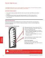
STEP THREE:
Clean the Tank
Use tap water to flush loose minerals from the tank:
•
Sediment screen at tank’s bottom is removable.
•
For a more thorough cleaning, soak tank in water
with CLR
®
, LimeAway
®
or white vinegar. Then
rinse clean.
•
Tank is dishwasher safe.
•
Do not use hydrocarbon-based cleaners.
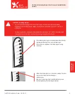
Unplug the power cord and carefully rub minerals off of
the heating element and tank walls. Clear the sensor
compartment holes of debris, if present.
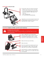
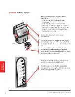
STEP FOUR:
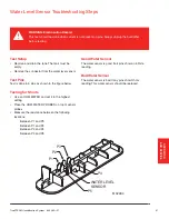
Replace the Water Level Sensor (if necessary)
WARNING: Electrocution Hazard.
TrueSTEAM must be unplugged before removing the cover. Hazardous voltage could cause
death or serious injury.
Remove TrueSTEAM cover and inspect water
level sensor. If debris buildup is present, clean with
recommended cleaning agent. If cracks or visible
discoloration is noticed, replace sensor (see below).
Remove T-30 Torx screw and lift clamp.
Remove the sensor.
Ensure sensor gaskets are seated properly and are
in good condition (no cracks). If cracks are noticed,
replace water sensor assembly (including gaskets).
Install a new sensor if excessive mineral deposits are
present, or if gaskets are in poor condition.
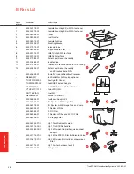
See “Parts
List” on page 59.
M29631
M29632
TrueSTEAM Humidification System 69-2285—01
49
2
1
3
4
2
5
1


