background image

9

31-00426 | Rev.10-20

Switch Mode Power Supply 

To reduce overall current consumption, the GW-1000-

WE/GW-1000-NWE gateway can be powered by a switch 

mode dc power supply (rather than by a transformer). 

Fusing 

The choice of appropriate fusing is dependent upon the 

given connection scenario (i.e., cable lengths and the use 

of a primary and/or secondary transformer) and upon the 

type of connected bus. 

WIRING AND SET-UP

General Safety Considerations

• When connecting the GW-1000-WE/GW-1000-NWE 

gateway, VDE, National Electric Code (NEC) or 

equivalent, and any local regulations concerning 

grounding must be observed. 

• Only qualified electricians may carry out electrical work. 

• The electrical connections must be made at the 

terminals of the GW-1000-WE/GW-1000-NWE 

gateway. 

• For Europe, only: To comply with CE requirements, 

devices with a voltage in the range of 50 to 1000 Vac or 

75 to 1500 Vdc and which are not provided with a supply 

cord and plug or with other means for disconnection 

from the supply having a contact separation of at least 3 

mm in all poles must have the means for disconnection 

incorporated in the fixed wiring.

• Only copper conductors should be used for electrical 

connection. 

• Only electrical cables/wires with operating temperature 

at least 75° C should be used for electrical connection.

WARNING

Risk of electric shock or equipment damage! 

• Do not touch any live parts in the cabinet. 

• Disconnect the power supply before making 

connections to or removing connections from Gateway 

terminals. 

• Do not use spare terminals as wiring support points. 

• Do not reconnect the power supply until you have 

completed the power supply.

CAUTION

Observe the precautions for handling 

electrostatic devices.

Wiring Terminals 

The GW-1000-WE/GW-1000-NWE gateway features 

screw-type terminals.

Terminals support both flexible and solid cables. Wires can 

be equipped additionally with ferrules.

Connecting Power Supply 

Connect the power supply to the power supply terminals of 

the GW-1000-WE/GW-1000-NWE gateway. 

The factory default Gateway must be powered ON for a 

minimum of 10 hours for the first time to make the RTC 

function as intended. 

Earth Grounding 

The GW-1000-WE/GW-1000-NWE gateway comply with 

SELV (Safety Extra-Low Voltage), so protective earth 

grounding is not required. However, a functional earth 

grounding for EMC is mandatory. For information, see 

“Appendix: Earth Grounding” section on page 13.

Table 14. Fusing

Designation

Description

F1 

4 A, time-lag fuse (slo-blow), e.g., 

Littlefuse type 218.004. 

F2 

Depends upon field devices. 

Table 15. Power Supply Wiring Terminals Specifications

Terminal 

Type

Stripping 

Length

 Torque 

Value

Max. Plug Gauge

Screw

(Type P2)

6mm

3.1 to 

3.5 lb-in

(0.350 

to 0.395 

N-m)

28 to 14 AWG 

(0.0804-2.075 
mm

2

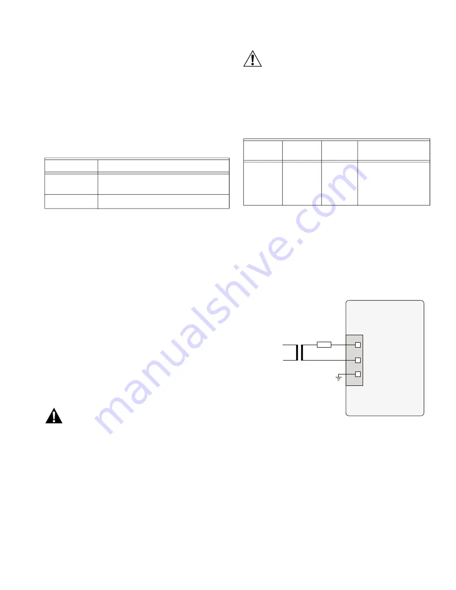
GW-1000-WE/

GW-1000-NWE

110VAC/230VAC

24VAC

24V0

24V~

FGND

F1

Содержание GW-1000-NWE

Страница 1: ...INSTALLATION INSTRUCTIONS SMB Gateway GW 1000 WE GW 1000 NWE ...

Страница 2: ...n conformance FEATURES Integrated with Small and Medium Building Administrator Supervisor Dashboard built on Honeywell Forge cloud platform Configurable via the Honeywell Connect Mobile app Integrated with Honeywell Thermostat TC500A N TC500A W and Honeywell Smart IO IO 10MIXR NWE IO 10MIXR WE via BACnet secured Compatible with MultiTech LoRaWAN hub Compatible with R718A R718CT and R718G sensors S...

Страница 3: ... Power supply 24 Vac dc RS485 Interface 3 Terminals 2 CH3 for RS485 interface 3 CH3 for RS485 interface 3 GND3 GND3 for RS485 interface 3 RS485 Interface 2 Terminals 3 CH2 for RS485 interface 2 CH2 for RS485 interface 2 GND2 GND2 for RS485 interface 2 RS485 Interface 1 Terminals 4 CH1 for RS485 interface 1 CH1 for RS485 interface 1 GND1 GND1 RS485 interface 1 LED 5 Tx1 LED green Transmit and recei...

Страница 4: ... 5 Tx3 LED green Transmit and receive indication for RS485 interfaces 1 to 3 Rx3 LED green 6 Main LED Indicates the operational status of the Gateway RJ45 Interface 7 Ethernet 1 Dedicated to Internet Cloud connectivity 10 100 1000BASE T 8 Ethernet 2 Dedicated to MultiTech LoRaWAN hub 10 100 1000BASE T SMA Terminal 9 For Wi Fi and Bluetooth antenna Antenna for both Wi Fi and Bluetooth 802 11a b g n...

Страница 5: ...otocol version IEEE 802 3 Testing Electrical Components IEC68 Certification UL60730 1 UL916 EN 60730 1 EN 60730 2 9 FCC Part15 Subpart B CAN ICES 3 B NMB 3 B BQB RoHS II REACH System Transformer The system transformer s must be safety isolating transformers according to IEC 61558 2 6 In the U S A and Canada NEC Class 2 transformers must be used Table 6 Operating Environment Ambient Operating Tempe...

Страница 6: ...t 100 ft Supported type of Wi Fi connections Wi Fi Access Point Providing access point to IO 10MIXR WE IO 10MIXR NWE Smart IO and TC500A N Commercial Thermostat devices Table 8 Gateway Parameters Max number of points 3000 Max trend retention 2 days 1 min samples Max number of alarms retained 70000 Records History push Per Minute GW OTA Upgrade check Once in 4 hours Devices OTA Upgrade check Once i...

Страница 7: ...nded Terminal Covers Large Pack Quantity of 4 ANT REM Remote Antennas with adhesive magnetic foot for wireless communication 1 5 meter 4 9 feet cable length for remote mounting of the antenna Pack Quantity of 4 Ferrite Ring Part Number ZCAT3035 1330 BK Manufacture TDK GW ANT LOC Local Antennas optional not included in the kit MPN ANT DB1 LCD SMA Manufacturer LINX Technologies Pack Quantity of 4 Ta...

Страница 8: ...0100 or EN 60204 1 for earth grounding Use only accessory equipment that comes from or has been approved by Honeywell It is recommended that devices be kept at room temperature for at least 24 hours before applying power This is to allow any condensation resulting from low shipping storage temperatures to evaporate The GW 1000 WE GW 1000 NWE Gateway must be installed in a manner e g in a lockable ...

Страница 9: ...height of max 45 mm It is suitable for panel rail mounting on 35 mm standard panel rail both horizontal and vertical rail mounting possible The GW 1000 WE GW 1000 NWE is used for the purpose of building HVAC control and is suitable for use only in non safety controls for installation on or in appliances Table 12 Safety Information as per EN60730 1 Electric Shock Protection PELV Pollution Degree Po...

Страница 10: ...visor Dashboard 8 Honeywell Connect Mobile App 8 POWERSUPPLY 8 Transformers 8 Switch Mode Power Supply 9 Fusing 9 Wiring andSet up 9 General Safety Considerations 9 Wiring Terminals 9 Connecting Power Supply 9 Earth Grounding 9 WIRINGCONNECTIONS 10 Gateway to MultiTech LoRaWAN hub connection 10 WirelessConnectivity 11 Connectivity Frequency Range 11 General Information 11 Dimensions 12 GW 1000 WE ...

Страница 11: ...vant technology not readily available to average consumer Only a person professionally trained in the technology is competent This device is not directly marketed or sold to general public Safety Information as per EN60730 1 The GW 1000 WE GW 1000 NWE gateway is intended for residential commercial and light industrial environments The GW 1000 WE GW 1000 NWE gateway is an independently mounted elec...

Страница 12: ...ity non condensing Ambient Storage Temperature 28 9 to 70 C 20 to 158 F Ambient Storage Humidity 5 to 95 relative humidity non condensing Vibration Under Operation 0 024 double amplitude 2 to 30 Hz 0 6 g 30 to 300 Hz Dust Vibration According to EN60730 1 RFI EMI Residential commercial and light industrial environments MTBF Mean Time Between Failure 11 5 years Table 6 Default IP Address IP Address ...

Страница 13: ...er supply 24 Vac dc RS485 Interface 3 Terminals 2 CH3 for RS485 interface 3 CH3 for RS485 interface 3 GND3 GND3 for RS485 interface 3 RS485 Interface 2 Terminals 3 CH2 for RS485 interface 2 CH2 for RS485 interface 2 GND2 GND2 for RS485 interface 2 RS485 Interface 1 Terminals 4 CH1 for RS485 interface 1 CH1 for RS485 interface 1 GND1 GND1 RS485 interface 1 LED 5 Tx1 LED green Transmit and receive i...

Страница 14: ... expansion modules 24V0 FGND GND for RS485 interface 4 for RS485 interface 4 RJ11 Interface 11 for RS485 interface 5 for RS485 interface 5 output 5Vdc GND USB Interface 12 Micro USB port to connect with laptops mobile and tablets 13 USB Type A port Reset Button 14 Reset button to reset the device to factory default Table 8 Gateway Terminals Continued Type Legend Signal Comment Table 9 Main LED Pat...

Страница 15: ...t interfaces 1 and 2 Case LED Behavior Meaning Remedy 1 Yellow LED is ON steadily Ethernet is working with connectivity up to 100Mbps If communication problems persist then check the green LED See Case 3 and Case 4 given below 2 Yellow LED is OFF If the green LED is ON or flashing then Ethernet is working with connectivity up to 10Mbps If the green LED is OFF then Ethernet is disconnected Connect ...

Страница 16: ...000 WE GW 1000 NWE gateways to the same transformer Transformers Honeywell Transformers A transformer can power the GW 1000 WE GW 1000 NWE gateway When determining total current consumption and selecting the appropriate transformer take into account the number of connected modules accessories and field devices NOTE In Europe system transformer s must be safety isolating transformers according to I...

Страница 17: ...connection WARNING Risk of electric shock or equipment damage Do not touch any live parts in the cabinet Disconnect the power supply before making connections to or removing connections from Gateway terminals Do not use spare terminals as wiring support points Do not reconnect the power supply until you have completed the power supply CAUTION Observe the precautions for handling electrostatic devi...

Страница 18: ...o not connect the MultiTech LoRaWAN Hub to Ethernet 1 If connected to Ethernet 1 mistakenly then restart the MultiTech LoRaWAN Hub before connecting to Ethernet 2 TX 5V GND Isola on Barrier RX 5V_ISO GND_ISO RS485 RS485 24V 24V0 FGND CH1 CH1 GND1 GW 1000 WE GW 1000 NWE Ethernet 1 Ethernet 2 Mul Tech LoRaWAN Hub Ethernet 5VDC ...

Страница 19: ... RF exposure compliance FCC Class B Statement NOTE This equipment has been tested and found to comply with the limits for a Class B digital device pursuant to part 15 of the FCC Rules These limits are designed to provide reasonable protection against harmful interference in a residential installation This equipment generates uses and can radiate radio frequency energy and if not installed and used...

Страница 20: ...GATEWAY GW 1000 WE GW 1000 NWE 31 00426 Rev 10 20 12 DIMENSIONS GW 1000 WE GW 1000 NWE Gateway 59 mm 2 323 110 mm 4 331 45 mm 1 772 52 mm 2 047 135 mm 5 315 145 8 mm 5 744 ...

Страница 21: ... ELECTRICAL IMPACT EN60204 1 is not mandatory this is because electrical safety is provided by the use of SELV and transformers according to standard EN60742 SAFETY AGAINST UNEXPECTED START UP OF ROTATING MOVING MACHINES If the application plant does not contain machines that can be harmful to the operator due to an unexpected start up the standard EN60204 1 is not applicable If such machines are ...

Страница 22: ...ce Table 18 Accessories Part Number Description GW TCVR Replacement Terminal Covers Small Pack Quantity of 4 GW EXT TCVR Extended Terminal Covers Large Pack Quantity of 4 ANT REM Remote Antennas with adhesive magnetic foot for wireless communication 1 5 meter 4 9 feet cable length for remote mounting of the antenna Pack Quantity of 4 Ferrite Ring Part Number ZCAT3035 1330 BK Manufacture TDK GW ANT...

Страница 23: ...a été approuvé par Innovation Sciences et Développement économique Canada pour fonctionner avec les types d antenne énumérés cidessous et ayant un gain admissible maximal Les types d antenne non inclus dans cette liste et dont le gain est supérieur au gain maximal indiqué pour tout type figurant sur la liste sont trictement interdits pour l exploitation de l émetteur Hub and Sensors MultiTech LoRa...

Страница 24: ...vice TC500A N Commercial Thermostat Datasheet 31 00398M 1 Product data of the device TC500A N Commercial Thermostat Mounting Instructions 31 00399M 1 Describes the mechanical mounting and basic wiring of the device TC500A N Commercial Thermostat User Guide 31 00400M 1 Contains procedures for UI based functionalists of the device TC500A N Commercial Thermostat Quick Start Guide 31 00401M 1 Contains...

Отзывы: