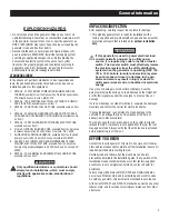
background image

2

GENERAL HAZARDS

For safety reasons, the manufacturer recommends that this 

• 

equipment be installed, serviced and repaired by a Service 
Dealer or other competent, qualified electrician or installation 
technician who is familiar with applicable codes, standards 
and regulations. The operator also must comply with all such 
codes, standards and regulations.

The engine exhaust fumes contain carbon monoxide, which 

• 

can be DEADLY. This dangerous gas, if breathed in sufficient 
concentrations, can cause unconsciousness or even death. 
Do NOT alter or add to the exhaust system or do anything that 
might render the system unsafe or in noncompliance with 
applicable codes and standards.
Install a battery operated carbon monoxide alarm indoors, 

• 

according to manufacturer’s instructions/recommendations.
Adequate, unobstructed flow of cooling and ventilating air 

• 

is critical to correct generator operation. Do not alter the 
installation or permit even partial blockage of ventilation 
provisions, as this can seriously affect safe operation of the 
generator. 

The generator MUST be installed and operated 

outdoors only.

Keep hands, feet, clothing, etc., away from drive belts, fans, 

• 

and other moving or hot parts. Never remove any drive belt or 
fan guard while the unit is operating.
When working on this equipment, remain alert at all times. 

• 

Never work on the equipment when physically or mentally 
fatigued.
Inspect the generator regularly, and contact the nearest Dealer 

• 

for parts needing repair or replacement.
Before performing any maintenance on the generator, 

• 

disconnect its battery cables to prevent accidental start up. 
Disconnect the cable from the battery post indicated by a 
NEGATIVE, NEG or (–) first, then remove the POSITIVE, POS 
or (+) cable. When reconnecting the cables, connect the 
POSITIVE cable first, the NEGATIVE cable last.
Never use the generator or any of its parts as a step. Stepping 

• 

on the unit can stress and break parts, and may result in 
dangerous operating conditions from leaking exhaust gases, 
fuel leakage, oil leakage, etc.

ELECTRICAL HAZARDS

All generators covered by this manual produce dangerous 

• 

electrical voltages and can cause fatal electrical shock. Utility 

power delivers extremely high and dangerous voltages to 

the transfer switch as does the standby generator when it 

is in operation. Avoid contact with bare wires, terminals, 

connections, etc., while the unit is running. Ensure all 

appropriate covers, guards and barriers are in place, secured 

and/or locked before operating the generator. If work must 

be done around an operating unit, stand on an insulated, dry 

surface to reduce shock hazard.

Do not handle any kind of electrical device while standing 

• 

in water, while barefoot, or while hands or feet are wet. 

DANGEROUS ELECTRICAL SHOCK MAY RESULT.

The National Electrical Code (NEC) requires the frame and external 

• 

electrically conductive parts of the generator to be connected to 

an approved earth ground. Local electrical codes also may require 

proper grounding of the generator electrical system.

After installing this home standby electrical system, the 

• 

generator may crank and start at any time without warning. 

When this occurs, load circuits are transferred to the STANDBY 

(generator) power source. To prevent possible injury if such 

a start and transfer occur, always set the generator’s AUTO/

OFF/MANUAL switch to its OFF position before working on 

equipment and remove the 15A fuse from the generator control 

panel.

In case of accident caused by electric shock, immediately shut 

• 

down the source of electrical power. If  this is not possible, 

attempt to free the victim from the live conductor. AVOID DIRECT 

CONTACT WITH THE VICTIM. Use a nonconducting implement, 

such as a dry rope or board, to free the victim from the live 

conductor. If the victim is unconscious, apply first aid and get 

immediate medical help.

Never wear jewelry when working on this equipment. Jewelry 

• 

can conduct electricity resulting in electric shock, or may get 

caught in moving components causing injury.

FIRE HAZARDS

For fire safety, the generator must be installed and maintained 

• 

properly. 

Installation must always comply with applicable 

codes, standards, laws and regulations.

 Adhere strictly 

to local, state and national electrical and building codes. 

Comply with regulations the Occupational Safety and Health 

Administration (OSHA) has established. Also, ensure that the 

generator is installed in accordance with the manufacturer’s 

instructions and recommendations. Following proper 

installation, do nothing that might alter a safe installation and 

render the unit in noncompliance with the aforementioned 

codes, standards, laws and regulations.

Keep a fire extinguisher near the generator at all times. 

• 

Extinguishers rated “ABC” by the National Fire Protection 

Association are appropriate for use on the standby electric 

system. Keep the extinguisher properly charged and be 

familiar with its use. Consult the local fire department with any 

questions pertaining to fire extinguishers.

Safety Rules

Содержание Generator

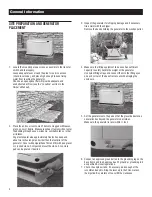
Страница 1: ...855 GEN INFO INSTALLATION GUIDELINES Air cooled Generators ...

Страница 2: ...as Induction Motors sump pumps refrigerators air conditioners furnaces etc Electronic Components computer monitor TV etc Lighting Loads and Microwaves READ THIS MANUAL THOROUGHLY If any portion of this manual is not understood contact the nearest Dealer for starting operating and servicing procedures Throughout this publication and on tags and decals affixed to the generator DANGER WARNING CAUTION...

Страница 3: ...se Instructions The manufacturer suggests that these rules for safe operation be copied and posted near the unit s installation site Safety should be stressed to all operators and potential operators of this equipment Study these SAFETY RULES carefully before installing operating or servicing this equipment Become familiar with this Owner s Manual and with the unit The generator can operate safely...

Страница 4: ...l appropriate covers guards and barriers are in place secured and or locked before operating the generator If work must be done around an operating unit stand on an insulated dry surface to reduce shock hazard Do not handle any kind of electrical device while standing in water while barefoot or while hands or feet are wet DANGEROUS ELECTRICAL SHOCK MAY RESULT The National Electrical Code NEC requi...

Страница 5: ...unpacking carefully inspect the contents for damage This standby generator set is ready for installation with a factory supplied and pre mounted base pad and has a weather protective enclosure that is intended for outdoor installation only If this generator is used to power electrical load circuits normally powered by a utility power source it is required by code to install a transfer switch The t...

Страница 6: ...rushed stone Compact and level the stone A concrete pad can be poured if desired 3 Inspect the generator for shipping damage and if necessary file a claim with the shipper Remove the bands holding the generator to the wooden pallet 4 Make sure the lifting equipment to be used has sufficient capacity to safely handle the weight of the generator Use nylon lifting straps and connect them to the lifti...

Страница 7: ... LP position INSTALLING CONNECTING GAS LINES 1 Both natural gas and LP Vapor are highly volatile substances so strict adherence to all safety procedures codes standards and regulations is essential Gas line connections should be made by a certified plumber familiar with local codes Always use AGA approved gas pipe and a quality pipe sealant or joint compound Verify the capacity of the natural gas ...

Страница 8: ...lator ports inside the generator to make sure there s enough pressure for proper generator operation The local gas supplier is responsible for ensuring adequate pressure so if the pressure is too low or if it s greater than 14 inches of water column contact the gas supplier 7 When finished checking the gas pressure close the manual shutoff valve GENERATOR ACTIVATION When battery power is applied t...

Страница 9: ...ation code wait 3 5 seconds for the next display ENTER ACTIVATION CODE Passcode TROUBLESHOOTING Display Reads Use ARROW keys to scroll and find the first number of your Activation Code Press ENTER to select Repeat this step until all digits have been entered Use ESCAPE to correct previous digits Display Reads Activation is complete when all digits are entered above and your screen shows this displ...

Страница 10: ...wer leads to the circuit breaker 6 Now connect the red and black power leads to the circuit breaker Since this is a single phase application it doesn t matter which wire is connected to which lug 7 Connect the green equipment ground wire to the ground bus bar and torque to 35 inch lbs The torque values are 10 14 AWG 35 in lbs 8 AWG 40 in lbs 4 6 AWG 45 in lbs T1 N2 N1 209 210 0 194 23 NEUT G N D 8...

Страница 11: ...asing a battery for the generator refer to the Owner s Manual for the recommended battery Group 26R 12 Volt 525cca minimum 2 Follow all of the procedures and safety precautions in the generator Owner s Manual when installing the battery Verify the switch is in the off position When preparing for operational testing DO NOT connect the battery until transfer switch connections are complete APPENDIX ...

Страница 12: ...1 The generator powers only designated circuits that are grouped together and wired into a separate priority distribution panel The transfer switch is installed between the main distribution panel and the priority panel The amperage rating of the transfer switch must be equal to or greater than the highest amperage rating of the utility and generator breakers feeding the switch WHOLE HOUSE CIRCUIT...

Страница 13: ...utility to the appropriate lugs in the transfer switch The lugs are clearly marked in the switch N Normal Utility Supply E Generator Connection Panel T Load Distribution Panel 2 Neutral wires from both the utility and the generator are connected to the same neutral lug in the switch 3 Connect the control wires from the generator to the designated locations Wires 0 23 and 194 connect to the termina...

Страница 14: ...minations Repeat the same voltage checks on terminals T1 and T2 to make sure current is flowing properly through the contactor 4 Switch the generator s main circuit breaker OFF and put the mode switch in the OFF position 5 Make sure utility power is OFF and place all of the individual circuit breakers in the main distribution panel in the OFF position 6 Locate the transfer handle insert the metal ...

Страница 15: ...still OFF use the transfer handle to move the main contacts to the UP utility position 11 Close the main breaker to turn utility power ON 12 Switch the generator s main breaker to the ON position and put the mode switch in AUTO 13 Shut OFF utility power and make sure the generator starts automatically after the line interrupt delay 14 Switch the utility breaker to ON and make sure that power is au...

Страница 16: ...off 19 Shut OFF utility power again The generator should start and the entire priority load should transfer to the generator 20 Close the main breaker to restore utility power and allow the engine to cool down and shut itself off Operational tests are now complete Refer to Appendix E Setting the Automatic Exercise Function to complete the installation APPENDIX B DIGITAL LOAD MANAGEMENT DLM 1 To co...

Страница 17: ...n and the sequence repeats However the level that caused the overload and all levels higher will not be enabled again for 30 minutes Control of Air Conditioner Load 1 Route the thermostat cable from the furnace thermostat to the outdoor air conditioner unit to the transfer switch 2 Connect the wire to the terminal strip terminals Air 1 on the LSM as shown in Figure 2 2 These are normally closed co...

Страница 18: ...NG NEUTRAL AND ENCLOSURE NEUTRAL BONDED DISCONNECT BUSBAR BETWEEN 600 Volt 5 amp type and rating Replace with UL listed fuse of same 0D3587 0G4220 0G9651A CONNECTIONS SOURCE UTILITY N1 N2 UPPER LOWER 0 GROUND 15B 12V 23TRANSFER AIR 1 AIR 2 PRIORITY 1 PRIORITY 2 PRIORITY 3 PRIORITY 4 T1 NEUTRAL CONTACTOR 1 CONTACTOR 2 CONTACTOR 3 CONTACTOR 4 WARNING CUSTOMER CONNECTION NOTE WIRE ORIENTATION 0G8137 ...

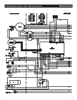
Страница 19: ...17 Wiring Diagram Schematic 15kW Drawing No 0H6198 D Electrical Data ...

Страница 20: ...18 Electrical Data Wiring Diagram Schematic 15kW Drawing No 0H6198 D ...

Страница 21: ...19 Wiring Diagram Schematic 15kW Drawing No 0H6198 D Electrical Data ...

Страница 22: ...20 Electrical Data Wiring Diagram Schematic 20kW Drawing No 0H7570 B ...

Страница 23: ...21 Wiring Diagram Schematic 20kW Drawing No 0H7570 B Electrical Data ...

Страница 24: ...22 Electrical Data Wiring Diagram Schematic 20kW Drawing No 0H7570 B ...

Страница 25: ...23 Wiring Diagram Schematic 10kW Drawing No 0J2939 B Electrical Data ...

Страница 26: ...24 Electrical Data Wiring Diagram Schematic 10kW Drawing No 0J2939 B ...

Страница 27: ...25 Wiring Diagram Schematic 10kW Drawing No 0J2939 B Electrical Data ...

Страница 28: ...Power Systems S45 W29290 Hwy 59 Waukesha WI 53187 1 855 GEN INFO honeywellgenerators com The Honeywell Trademark is used under license from Honeywell International Inc Honeywell International Inc makes no representation or warranties with respect to this product ...

Отзывы: