S3 Series UL Listing Document —
P/N LS10005-051GF-E:D3 3/09/2016
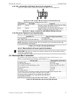
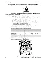
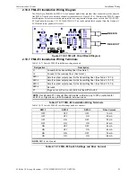
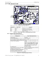
17
Signaling Line Circuit (SLC) (SLC-PM/SLC95-PM)
Installation Wiring
2.6 Signaling Line Circuit (SLC) (SLC-PM/SLC95-PM)
The SLP panel provides the option of either of the following Loop Cards:
•
SLC-PM (Signaling Line Circuit-Personality Module)
The SLC-PM is used with the System Sensor devices.
•
SLC95-PM (Signaling Line Circuit 95-Personality Module)
The SLC95-PM is used with the Apollo devices
.
2.6.1 Signaling Line Circuit Wiring and Ratings
!
WARNING: SLC-PM/SLC95-PM RESTRICTION:
DO NOT COMBINE THE SLC-PM AND THE SLC95-PM ON THE SLP MAIN BOARD.
- DETECTOR SPACING MUST MEET NFPA 72 REQUIREMENTS
- THE ALARM VERIFICATION FEATURE IS BLOCKED FROM BEING APPLIED TO DEVICES
USED IN POINT AND GROUP CROSS ZONES BY CAMWORKS.
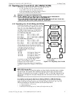
The SLP-E3 provides up to two 24 VDC Class A, Style 6,
Style 7 or four Class B, Style 4 signaling line circuits. See
Figure 2.6.1.1 for wiring information. Style 7 (Class X)
wiring requires the use of an M500X Isolator Module
(SLC-PM), or XP95-LI Line Isolator or XP95-LIB Line
Isolator Base (SLC95-PM) on both sides of a device.
Figure 2.6.1.1 Signaling Line Circuits
SLC-PM Wiring Instructions
SLC 1 Style 4
TB1-1 (+), TB1-2 (-) OUT
SLC 2 Style 4
TB1-1 (+), TB1-2 (-) OUT
SLC 1 Style 6
TB1-3 (+) OUT, TB1-4 (-) RETURN
SLC-2 Style 6
TB1-3 (+) OUT, TB1-4 (-) RETURN
SLC95-PM Wiring Instructions
SLC 1 Style 4
TB1-1 (+), TB1-2 (-) OUT
SLC 2 Style 4
TB1-1 (+), TB1-2 (-) OUT
SLC 1 Style 6
TB1-3 (+) OUT, TB1-4 (-) RETURN
SLC-2 Style 6
TB1-3 (+) OUT, TB1-4 (-) RETURN
(Polarity markings indicate the polarity that should be
maintained throughout the circuit. Polarity connected to the
circuit must be observed on all devices).
SLC-PM/SLC95-PM Circuit Ratings
24 VDC (nominal)
Currents:
SLC-PM
0.014 amp max. (Supervisory)
SLC-PM
0.014 amp max. (Alarm)
SLC95-PM
0.016 amp max. (Supervisory)
SLC95-PM
0.016 amp max. (Alarm)
40 Ohms max. line impedance
0.5 µf max. line capacitance
Ground fault test impedance: Zero Ohms
Wiring: 18 AWG minimum, twisted-pair, unshielded
Supervised, Class 2 Power-Limited
For additional information, refer to the Compatibility
Addendum for Gamewell-FCI Manuals, P/N: 9000-0427-
L8.
INPUT/CONTROL
MODULE
SMOKE/HEAT
CO/SENSOR
NCM-1
(SLC-PM only)
B (-)
A (-)
A (+)
B (+)
DOTTED LINES INDICATE CLASS A,
STYLE 6 WIRING.
B200S
SOUNDER BASE
(SLC-PM only)
NOTE: Drift Compensation:
The S3 Series contains a program that performs continuous testing of analog sensors, including
Sensitivity Tests. This program will compensate all analog sensors for age and environmental
conditions. If a problem occurs in a sensor, a “Failed Test”, “Dirty”, or “Very Dirty” indication for the
specific device will appear on the System Display and will be recorded in the Event Log and the
Serial Port.
Survivability for Addressable NAC Circuits Utilizing AOM-2SF or MMO-6SF Modules
Per the National Fire Alarm Code, NFPA 72, all circuits necessary for the operation of the notification
appliances shall be protected until they enter the evacuation signaling zone that they serve. Any of the
following methods shall be considered acceptable as meeting these requirements:
•
A 2-hour rated cable or cable system.
•
A 2-hour rated enclosure.
•
Performance alternatives approved by Authority Having Jurisdiction (AHJ).


