


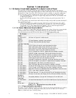


S3 Series UL Listing Document —
P/N LS10005-051GF-E:D3 3/09/2016
15
Initiating Device Circuit
Installation Wiring
2.3 Initiating Device Circuit
For information on the initiating device circuit, refer to Section 2.6, “Signaling Line Circuit (SLC) (SLC-
PM/SLC95-PM)”.
2.4 Notification Appliance Circuit (NAC)
The following subsections list the UL requirements for NACs and the corresponding E3 Series specifications.
2.4.1 Notification Appliance Circuit Wiring and Ratings
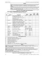
NOTES (Continued)
NOTE 3:
Normal operating current.During a power failure, current drops to 0.045 amp since backlight is
extinguished.
NOTE 4:
Add .003 amp for any LED to be lit for any condition when powered internally.
NOTE 5:
Add .003 amp for any LED to be lit for any condition when powered internally. When powered externally,
a max. output current of .050/point is available for a maximum total output of 2.4 amp/ANU-48.
NOTE 6:
For additional information on the System Sensor and Apollo device types and other Manufacturers’ device
currents, refer to the
Compatibility Addendum for Gamewell-FCI Manuals, P/N: 9000-0427-L8-L8
.
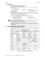
Table 2.2.5.1 SLP-E3 Standby Battery Calculation Chart (Continued)
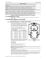
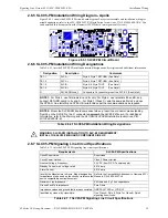
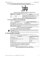
The S3 Series panel provides two Class A, Style Z or four
Class B, Style Y notification appliance circuits. The NAC
Sync is optionally available for horn and strobe devices for all
NAC circuits using the configuration options in CAMWorks.
For more information, refer to the CAMWorks Online Help.
Figure 2.4.1.1 Notification Appliance
Circuits
See Figure 2.4.1.1 for wiring information.
For a list of the approved compatible devices, refer to the
Compatibility Addendum to Gamewell-FCI Manuals,
P/N: 9000-0427-L8-L8
.
Class B, Style Y
Class A, Style Z
NAC 1
TB1-1 (B+)
NAC 1
TB1-1 (B+)
NAC 1
TB1-2 (B-)
NAC 1
TB1-3 (A+)
NAC 2
TB1-5 (B+)
NAC 1
TB1-2 (B-)
NAC 2
TB1-6 (B-)
NAC 1
TB1-4 (A-)
NAC 3
TB1-3 (B+)
NAC 2
TB1-5 (B+)
NAC 3
TB1-4 (B-)
NAC 2
TB1-7 (A+)
NAC 4
TB1-7 (B+)
NAC 2
TB1-6 (B-)
NAC 4
TB1-8 (B-)
NAC 2
TB1-8 (A-)
Note:
Polarity markings indicate the polarity of the circuit in
alarm condition. Use UL Listed End-of-Line Resistor EOL-N
(33K), P/N: 4700-0484 for Class B, Style Y wiring.
Circuit Ratings:
24 VDC (Nominal)
Max. Alarm Load: 2.0 A/circuit Special Applications
Ground Fault Test Impedance: Zero Ohms
Supervised, Class 2 Power-Limited, 18 AWG minimum
NOTE:
NAC Synchronization: per circuit.
Coded Notification:
On board NAC circuits can provide Coded Notification.
Zone Coding allows an FACP to produce a distinct coded pattern on its NAC outputs, based upon the particu-
lar input device or cross zone that caused the alarm condition.
The S3 supports up to 63 different codes, each of which may be configured for any pattern of two, three, or
four digits. The digits may range from 1 to 14 pulses. Unique codes can be associated with individual input
devices and cross zones in the CAMWorks Configuration Program. Alternatively, multiple inputs may be
assigned to run the same code (up to a limit of 63 different codes).
EOL
B (-)
A (-)
A (+)
B (+)
- +
- +
DOTTED LINES INDICATE CLASS A,
STYLE Z WIRING. REMOVE EOL
FOR CLASS A, STYLE Z
OPERATION


