Honeywell FF-SRS5988 Скачать руководство пользователя страница 8

8

107018-04 EN FR26 GLO 1198 Printed in Germany

APPLICATION EXAMPLES (continued)

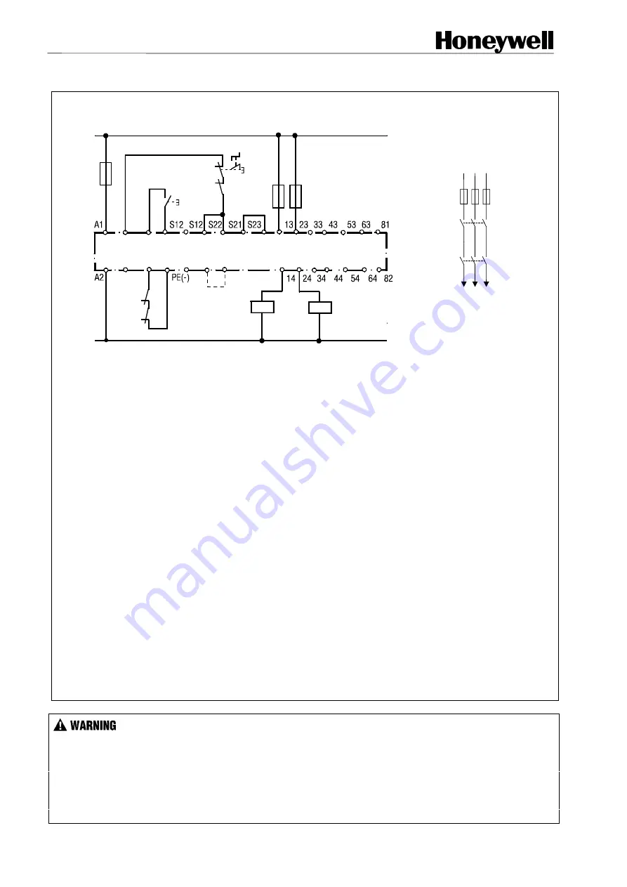
FIG 11.  SINGLE CHANNEL EMERGENCY STOP CIRCUITRY (WITH EXTERNAL CONTACTORS)

K4

K5

Start

L1

Honeywell

FF-SRS 5988

Emer-

gency

 stop

(A)

N

Y1 Y2

X1 X2

S33

S11

A3
(+)

S34

(B)

K4

K5

Machine Control

K4

K5

Fuses

L2 L3

L1

A4

(-)

(C)

Fuse

Fuses

This circuit has no redundancy in the emergency-stop control circuit and therefore offers a minor
safety level only.
CONTACT REINFORCEMENT VIA EXTERNAL CONTACTORS:

With switching current >10 A, the output contacts should be reinforced by external contactors (K4 and K5)
with positive-guided contacts. (see 

note (B)

)

1.  After activation of the E-stop push button, the two K2 and K3 LED’s will turn OFF, indicating that the two

internal safety relays K2 and K3 are de-energized. The normally open safety outputs 13/14..63/64 will
open and de-energize the external contactors K4 and K5. The normally closed monitoring output will
also close.

2.  After removing the stop condition, press and release the START push button to restart the safety control

module. If the two contactors K4 and K5 are working properly, the K2 and K3 LED’s will turn ON
indicating that the safety relays K2 and K3 are energized. The six normally open safety contacts will
close and the normally closed monitoring contacts will open allowing the machine to operate.

APPLICATION NOTES:

Note (A):

 SINGLE CHANNEL SAFETY DEVICES:

This may be a single output safety device such as a safety limit or interlock switch (for example: CLS, GK

and GSS).

Note (B): 

EXTERNAL CONTACTORS:

If contact reinforcement via external safety relays is necessary, the output contacts should be reinforced by
external safety relays. The proper operation of the external contactors must be monitored by looping the
NC contacts into the Final Switching Device (FSD) monitoring loop between terminals Y1/Y2.

Note (C):

 START MODE:

Manual start mode: Insert start push-button between S33/S34; no jumper must be set between X1/X2
Automatic start mode: Insert jumper between X1/X2

CONTACT MULTIPLICATION VIA EXTERNAL RELAYS

  If contact multiplication via external safety relays (or the FF-SRE3081 Extension module) is necessary,

connect one normally closed contact of each relay (or 81/82) in series into the Final Switching Device
monitoring loop (terminals Y1/Y2).

  Use two independent stop circuit safety relays with mechanically linked contacts to reliably detect a welded

contact.

 Failure to comply with these instructions could result in death or serious injury.

Содержание FF-SRS5988

Страница 1: ... or manual start mode cross fault monitoring and external relays monitoring APPROVALS CE The product packaging and documentation of FF SR Series products carry the CE mark following the examination by BG German Berufsgenossenschaft E MIII The CE declaration of conformity is available upon request cULus pending This product is pending approval by Underwriters Laboratories Inc according to Canadian ...

Страница 2: ... 00 Operating frequency 600 switching cycles hour Output contact fuse rating Time delay 6 A max Mechanical life Thirty million switching operations General Temperature range 15 C to 55 C 5 F to 131 F at 90 humidity max Sealing Housing IP 40 Terminals IP 20 Housing material Thermoplastic Vibration resistance Amplitude 0 35 mm Frequency 10 to 55 Hz Wire connector connection 1 x 4 mm 2 solid max 12 A...

Страница 3: ...Y Control Reliability means that the device system or interface shall be designed constructed and installed such that a single component failure within the device interface or system shall not prevent normal stopping action from taking place but shall prevent a successive machine cycle ANSI B11 19 1990 5 5 OSHA 29 CFR 1910 217 states that the control system shall be constructed so that a failure w...

Страница 4: ...AM PE S23 64 S21 K2 K23 K2 K1 K3 Power K2 K3 24V 14 24 34 44 54 82 K3 K2 K23 Overvoltage and short circuit protection Monitoring logic 23 A1 A2 A4 S11 A3 Y1 Y2 S 33 S 34 S 12 S 12 S 22 13 33 43 53 63 81 FUNCTIONAL DESCRIPTION In the manual start mode the module accepts input from the safety device light curtain safety mat safety switches etc between S11 S12 and S21 S23 after activation of the star...

Страница 5: ...The Power LED indicates power is applied to the safety control module Illuminated K2 and or K3 LED s indicate s that the corresponding internal safety relay is energized Both K2 and K3 relays must be energized to have the normally open contacts 13 14 63 64 in a closed position If one of the safety relays de energizes the normally closed contact will close FIG 8 MODULE FRONT PANEL K2 K 23 K3 13 A1 ...

Страница 6: ...eries or 81 82 inside the Final Switching Device FSD monitoring loop circuit Y1 Y2 This connection will ensure correct operation of the external relays or the Extension module after each FF SRS5988 activation If the FF SRS5988 is not activated often the customer is responsible for accomplishing any additional test procedures of the external safety components For instance this testing can be done b...

Страница 7: ...omatic start mode 1 After removing the stop condition the safety control module will reset within 1 sec The K2 and K3 LED s will turn ON indicating that the safety relays K2 and K3 are energized The six normally open safety contacts will close and the normally closed monitoring contact will open allowing the machine to operate APPLICATION NOTES NOTE A Dual channel safety devices This may be an eme...

Страница 8: ...cating that the safety relays K2 and K3 are energized The six normally open safety contacts will close and the normally closed monitoring contacts will open allowing the machine to operate APPLICATION NOTES Note A SINGLE CHANNEL SAFETY DEVICES This may be a single output safety device such as a safety limit or interlock switch for example CLS GK and GSS Note B EXTERNAL CONTACTORS If contact reinfo...

Страница 9: ...lly open safety outputs 13 14 63 64 will open relaying the stop condition to the machine control circuitry After closing the door S1 and S2 close and the internal relays K2 and K3 will energize The six normally open safety contacts will close and an external manual restart sequence may then be initiated allowing the machine to operate IMPORTANT NOTICES SAFETY LIMIT SWITCH SEQUENCE In order to let ...

Страница 10: ...Printed in Germany FIG 13 FF SRS5988 TROUBLESHOOTING FLOW DIAGRAM PAGE 1 OF 3 Machine Down Yes No Apply correct voltage Replace the safety module Yes Is the Power LED ON Is the power applied within specifications No Go to Figure 14 ...

Страница 11: ...le Ensure the FSD monitoring loop Y1 Y2 is closed when the external start push button is activated and opened when the pushbutton is released this tests the correct operation of the push button or optional external relays contactors Is the problem resolved Are the K2 and K3 LEDs ON Are the outputs contacts 13 14 63 64 closed and is 81 82 opened From Fig 15 Yes No No Go to Fig 15 From Fig 13 Ensure...

Страница 12: ...ween S12 A4 Disconnect S21 Is input channel two closed Also is there less than 68 Ohms between S21 S23 and more than 21 Vdc between S22 A3 Disconnect S11 and ensure input channel one is closed less than 68 Ohms between S11 S12 and more than 21 Vdc between S12 A4 No No Yes to all questions Yes Reconnect S11 Correct replace the external sensor s wiring supply voltage etc From Fig 14 Go to Page 2 Ens...

Страница 13: ...While we provide application assistance personally and through our literature and the Honeywell Website it is up to the customer to determine the suitability of the product in the application Specifications may change at any time without notice The information we supply is believed to be accurate and reliable as of this printing However we assume no responsibility for its use SALES AND SERVICE For...

Отзывы: