


Flame Safety, Ignition Components · Edition 12.20
EN-3
➔
Do not allow the scanner to operate at temperatures above the
manufacturer’s published limit. Scanners can be overheated by
high ambient temperatures, heat conducted and radiated from
burner and furnace surfaces, or a combination of the two.
➔
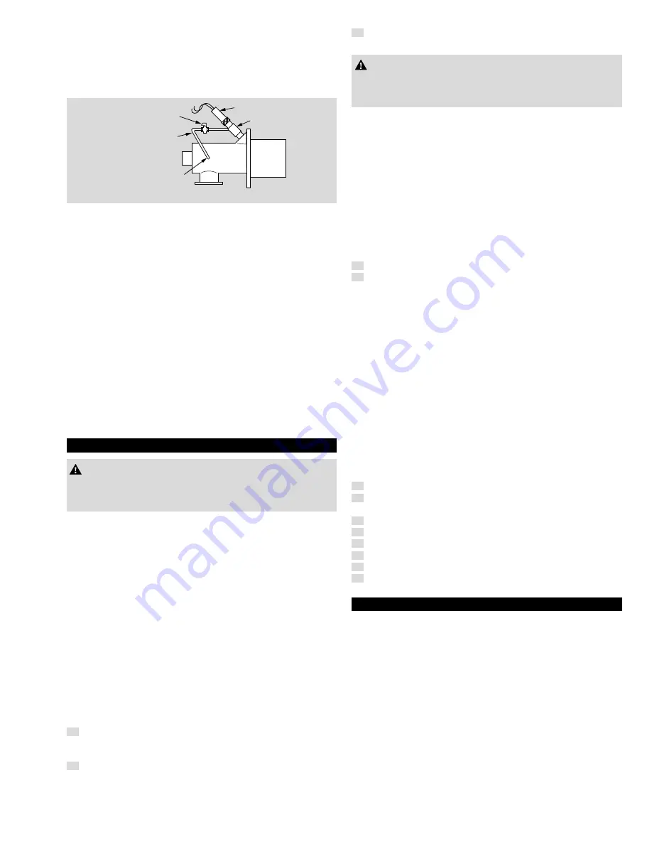
On most installations, scanners can be kept cool by purge air
blown into the scanner adaptor
Adjustable
Orifice
UV Scanner
Scanner
Adapter
Tubing
Connect Purge
Air Line to Burner
Air Housing Tap or
Combustion Air Line
(DO NOT connect to a preheated air line.)
Cooling the UV Scanner
Eclipse UV scanner adaptors and Heat Block Seals include tapped
connections for purge lines. The adjustable orifice cock in Figure
"Cooling the UV Scanner" permits setting the purge air at the opti-
mum flow rate.
On some burners, the scanner connection sights through the length
of the combustion air housing. The cold combustion air should suf-
fice to keep the scanner cool, so no additional purge air is required.
Preheated air burners pose a special problem, because the larger
amount of heat conducted and radiated from the burner can easily
overheat the scanner.
➔
Always use a Heat Block Seal such as Eclipe’s HBS on pre-
heated air burners. These adaptors include a quartz lense and
a non-metallic insulating nipple to reduce the heat conducted
back to the scanner.
➔
Cool purge air will probably also be required.
➔
In extreme cases, even these measures may not be sufficient, and
it may be necessary to use a radiation shield or to blow cooling
air over the scanner.
WIRInG
CAUtIon
Installation and trouble-shooting of flame supervisory circuits
should be done by qualified electricians, technicians or engineers
experienced in all facets of this type of control equipment.
electrical wiring compliances
➔
All the electrical wiring must comply with all applicable local codes
and/or standards such as NFPA Standard 70, IEC60364, CSA
C22, BS7671 and be acceptable to the local authority having
jurisdiction.
Handling flame supervisory components
➔
Exercise extreme caution in handling all flame supervisory com-
ponents. Many parts of the system operate at high voltage and
pose an electrocution hazard.
Follow manufacturer’s recommendations
Follow the flame detector manufacturer’s recommendations regarding
wire gauges, insulation grades and line lengths.
Wire type and length may weaken signal strength due to capacitive
coupling to ground.
On some installations, the wiring and its conduit may be exposed
to higher-than-normal temperatures. In these cases, use wiring with
high temperature insulation.
Wiring splices
1
Make as few wiring splices as possible between the detector and
its relay, as each splice is a potential source of current leakage
or grounding.
2
Make sure the bare wire ends at each splice are clean and not
oxidized. Secure splices with twist or crimp connectors, and tape,
if necessary, to ensure that no bare metal is exposed.
3
Make sure the connectors and tape are rated for the temperature
at the splice location.
CAUtIon
Use Caution regarding wires through boxes!
– Take care not to cut or nick the wires when pulling them
through conduit or junction boxes.
Wires from several Flame Detectors
➔
Wires from several flame detectors may be run together in a
common conduit, but do not place them in the same conduit with
high voltage ignition wires. Some manufacturers permit detector
lead wires in the same conduit as 120 VAC control wiring, but
may limit the length of run in a shared conduit. For longer runs,
separate conduits are required.
➔
Also, long runs may require shielding to prevent cross interference
and inducing a false signal onto a wire of a detector with no flame
from a detector wire that is sensing a flame.
➔
Make sure that you connect the flame sensor of a burner to the
electrical circuit of that burner.
Grounding
1
Make sure the flame relay is properly grounded.
2
UV scanners generally require grounding as well - this can be
done through the burner.
➔
However, if the scanner is mounted on a Heat Block Seal using
a non-metallic nipple, there will not be a ground connection to
the burner. Likewise, do not use non-conducting pipe dope on
scanner or adaptor threads.
➔
Likewise, do not use non-conducting pipe dope on scanner or
adaptor threads.
spark Interference
Electric spark ignition produces strong ultraviolet radiation. A UV
scanner can detect this radiation on some burners, either by direct
line of sight or by reflections from burner parts. Test the effect of
the ignition system on the flame signal and control sequence both
without and with flow of fuel to the burner. Flame rod signals can also
be affected due to electrical interference and sharing of the ground
connections. The signal may be increased, decreased or very erratic
while the ignition is on.
The following steps may help reduce spark interference:
1
Separate or shield the detector wiring from the ignition wiring.
2
Ensure proper grounding of the ignition transformer to burner
housing.
3
Reverse the wires feeding the primary to the ignition transformer.
4
Check for proper spark gap.
5
Clean, repair or replace faulty wiring and connectors.
6
Move the location of the ignition transformer.
7
Block UV scanner sighting with an orifice adapter.
8
Use a half-wave ignition transformer.
tRoUBLeLsHootInG
Refer to the product literature for the specific type of flame supervising
equipment in use. In addition, check that the installation was made
according to the recommendations in this operating instruction.


