43-TV-33-214 iss.2 GLO May 2015 UK
8
Re-assembling the Unit
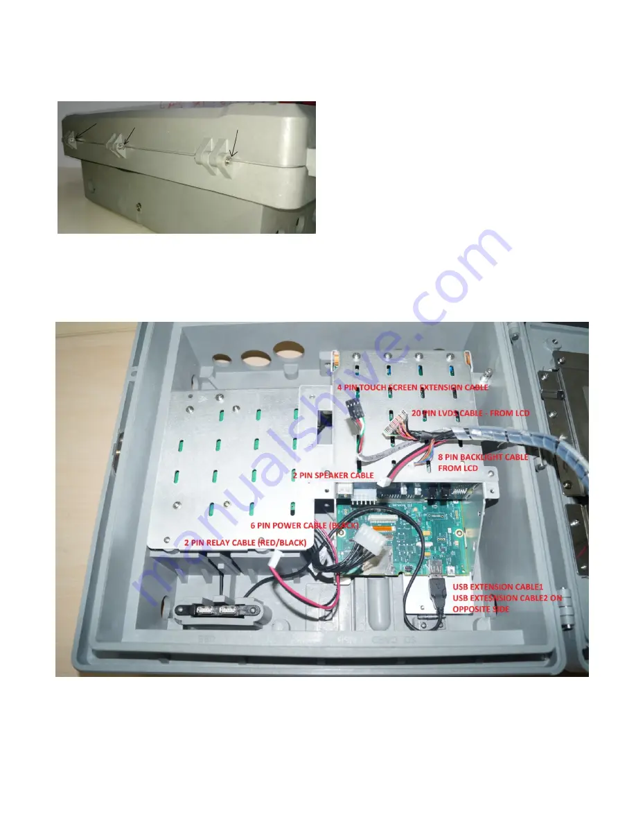
23. Put back the display bezel assembly on top of the case and insert the hinge pins shown by black arrows.
24. Attach the circlips to the hinge pins which lock the hinge pins in place.
25. Again open door to connect all the cables inside the case.
26. Figure 13 and the following table provide information on different cables used and where they should be connected.
Connectors of all the cables are polarized, make sure to connect the connectors as per notch direction.
Figure 13 – Cables to be connected inside slant chassis plate to the CPU board
Figure 12
Reconnecting hinge pins


