WEB-700 WEB-700-O CP-700
15
95-7776—01
WEB-700; WEB-700-O; CP-700
About Remote I/O Modules
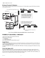
The WEB/CP-700 has an integral 6-pin connector to support remote I/O modules. The connector provides both 15Vdc power and
RS-485 communications to modules on that connected trunk, and is located on the right side of the unit.
Each remote I/O module has a DIN-mount base, and provides two (2) 6-pin connectors that allow you to “chain” multiple modules
together into one assembly. Table 3. lists the currently available modules.
About MiniPCI Cards
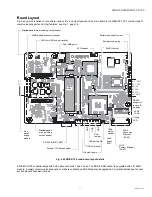
The WEB/CP-700 has one (1) available MiniPCI slot—see Fig. 5, page 11. At the time of this document, this is a “future use”
feature. At some later date, support may be added for WiFi applications using a MiniPCI card from an approved vendor.
WIRING DETAILS
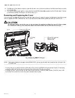
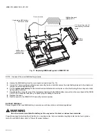
See Fig. 5, page 11 to locate connectors and other components on the WEB/CP-700 controller.
Make connections to the WEB/CP-700 in the following order.
1.
Install any option board (LON, RS-485, RS-232, etc.) in the available option slots. See Installing an Option Card, page 13
for a procedure. For complete details, refer to the specific documentation that accompanied the option.
2.
Connect communications cables. See Communications Wiring, page 15 for ports available on the WEB/CP-700 base unit.
For ports on any installed option board (RS-232, LON, RS-485, modem) see the specific mounting and wiring guide for any
additional details.
3.
Apply power to the unit. See Power Up and Initial Checkout, page 22.
Communications Wiring
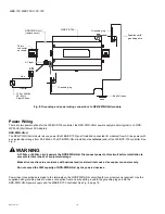
Communications ports on the WEB/CP-700 controller are primarily on the bottom side of the unit, with ports also on the right side
and top (Fig. 7). Communications port types include:
• Ethernet
• Serial
NOTE: Prior to connecting cables, provide strain relief for them to prevent damage to the controller.
Table 3. Remote I/O modules compatible with the WEB/CP-700
Model
Description
Notes
IO-16-REM-H Remote I/O RS-485 Module
DIN-mountable RS-485 comm
module that provides 16 points I/O,
with I/O point types as noted.
Provides the following I/O points:
•
8 - Universal Inputs (UIs).
•
4 - Digital Outputs (DOs), SPST-relay type.
•
4 - Analog Outputs, 0–10Vdc type.
Up to 16 (maximum) IO-16-REM-H accessory modules are supported.
Wiring is covered in a
separate
document, see the
IO-16-REM-H
Installation and Configuration Instructions
.


