Honeywell Comfort Window Скачать руководство пользователя страница 23

PCB0001C-01-BHP-PDII0614

4.   Single Heat Pump w/ 1 Additional Heater

The   fourth   category   of   wiring   configuration
schemes follows a single heat pump system,
with   1   additional   heater   in   the   system.     By
definition,   a   single   transformer   is   shared
between the RC1 and RH1 of the heat pump,
while   an   additional   transformer   (and
transformer   connection)   is   required   for   the
additional heater.
Optional   outputs   include   Cool/Heat   Stage   2
and Economizer Damper Control.  Refer to the
following charts while wiring up your system.
Note   that   E   should   not   be   connected   to
compressor   controls   as   there   are   not   any
minimum   compressor   on-times   built   into   the
controls for E.  Typically, E is connected to the
electric heat strips used for Emergency Heat
and   for   supplemental   heat   when   the   Heat
Pump is unable to keep up with the heating
demands of the current situation. 
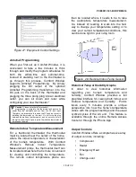
Please also note that it is important to record
how the reversing valve was wired up on your
previous thermostat.   This is controlled using
either B (typically blue), O (typically orange),
O/B, or B/O.   If B was wired up, this typically
means   that   the   reversing   valve   is   being
energized   during   heating   mode.     If   O   was
wired   up,   the   reversing   valve   is   being
energized during cooling mode.  If O/B or B/O
was   wired   up,   it   is   important   to   check   your
existing thermostat to see if there is a jumper
or a setting which specifies how the reversing
valve was being energized (during cooling or
heating).   This setting must be applied to the
Comfort   Window   on   the   Equipment   Control
page.

Screw 

Terminal

Number

Connect To

Function

Std. 

Wire Color*

1

Jumper to 4

RC2

Red

2

Heater 2 Transformer

+24VAC

RH2

Red

3

Jumper to 4

RH1

Red

4

 Compressor

Transformer

+24VAC

RC1

Red

5

Compressor Control

Y

Yellow

6

Fan Control

G

Green

7

Emergency Heat

Control

E

White

8

Change-Over Control

B/O

Blue

12

Heater 2 Control

WH2

Dark Purple

15

-24VAC (Ground)

C

Brown/Black

**

16

Indoor Temp Probe

T1in

Black*

17

Indoor Temp Probe

T2in

Yellow*

19

Indoor Temp Probe

T3in

Red*

Screw 

Terminal

Number

Connect To

Function Proprietary 

Wire Color

10

Cool/Heat Stage 2

Control 

Y2

NA

11

Outside

Temp/Humidity Probe

OT2in

Yellow

13

Outside

Temp/Humidity Probe

OH1in

Green

14

Economizer Damper

Control

ECD

NA

16

Outdoor

Temp/Humidity Probe

OT1in

Black

18

Humidifier Output

HUM

NA

19

Outdoor

Temp/Humidity Probe

OT3in

Red

**Note:  Brown or Black are the most common
colors for 24VAC ground; however, white and
blue are also frequently used.

24 of 24

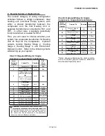
Chart 9: Required Wiring for Single Heat 
Pump w/ 1 Additional Heater Installations

Chart 10: Optional Wiring for Single Heat 
Pump w/ 1 Additional Heater Installations

*    

*    

*Caution!

  While there are some industry-wide

     color-coding conventions, some thermostat makers

     color-coding conventions, some thermostat makers
do not follow these conventions, so it is imperative to
record   the   previous   configuration   (both   color   and
function) so the correct wire can be connected to the
appropriate location on Comfort Window's wall-plate.

Содержание Comfort Window

Страница 1: ...y controls temperature it also controls humidity With ComfortWindow technology users can see at a glance whether their home is within their own personalized window of comfort taking into account humidity Comfort Window can also cool or heat their home even further into their window of comfort for free by utilizing outdoor air to cool or heat the home when it is possible to do so Not only does this...

Страница 2: ...onfiguration please refer to the Wiring Guide Section 5 If a ground wire has not already been pulled to the thermostat s location first see if there are any unused thermostat wires that you can use for Common C Otherwise it will be necessary to run an 18 GUAGE ONLY wire down the wall and feed it through the hole to the wall plate Screw Terminal Number Connect To Function Std Wire Color 0 Jumper to...

Страница 3: ... thermostat wire to pins 16 17 or 19 can permanently damage the thermostat and or remote temperature sensor 5 Install Thermostat onto Wall plate Slide thermostat through the keyed slots on each side of the wall plate mating the pins with the receptors until it rests flush with the wall 6 Re Apply Power Configure Thermostat Reconnect electricity at the breaker box If your system is something other ...

Страница 4: ...ch diagrams sequence below Set Date Time Touch the Settings icon and select the Set Date Time selection and set the date and time appropriately Note that Comfort Window automatically adjusts for Daylight savings time ext set the Date Time and set your Comfort 5 of 24 Figure 5 Equipment Controls Page Figure 6 Set Date Time Page ...

Страница 5: ...sh to start from a different starting point load a different sample program schedule using the internet controls online or on your smartphone Add as many or as few entries into the program as you desire by touching the Add button on the calendar home screen To edit any entry first select the entry in the calendar and then edit by touching the Edit button In the screen that appears specify the star...

Страница 6: ...ry can be associated with multiple days This makes it very easy to set up a program schedule from scratch 7 Override If you desire to temporarily override the thermostat s temperature setting simply touch the up or down arrow on the home screen In the screen that appears set the temperature to the desired level Specify the duration of the override by adding or decrementing the override time 7 of 2...

Страница 7: ... raw temperature reading This will enable you to concentrate on more important things in life rather than being bothered by changing your thermostat every time the humidity levels change within your home To help you visualize how the temperature and humidity levels in your home correspond to your personalized comfort settings Comfort Window also provides a quick way to view your home s current con...

Страница 8: ...ad Comfort Window will save that money by simply bringing outdoor air inside In fact there should be no more reason to manually open a window in order to drop the temperature in your home ever again as this process is completely automated Comfort Window not only automates this process but it carefully evaluates the outdoor air before bringing it indoors It is important to measure the humidity of t...

Страница 9: ...n the other hand will bring your home s temperature deeper into your window of comfort when it can virtually for free By utilizing outdoor air to heat or cool the inside of the home Comfort Window can bring you more comfort without turning on the compressor or the furnace For the minimal cost of running your system fan Comfort Window brings your home s temperature humidity point close to the cente...

Страница 10: ...be for multiple users who wish to have separate program schedules used on the thermostat Another example is someone who may have a schedule that does not follow a weekly pattern such as 2 weeks working followed by 2 weeks off For these cases Comfort Window provides a Save Schedule to Profile control and a Load Schedule Profile control To save the current Program Schedule to a given Profile use the...

Страница 11: ... be stored on the cloud to be accessed by any internet connected device of your choosing By enabling the Analyze Anywhere feature you agree to our standard terms and conditions Wireless settings are easy to set up and work out of the box Comfort Window supports many different over the air encryption protocols including WEP 128 WPA PSK TKIP and WPA2 PSK AES and Comfort Window automatically determin...

Страница 12: ... a power failure your thermostat s date and time will recover automatically The Remote Access Center also enables a remote firmware update feature through the Devices Edit Check for Firmware Updates link If you enable the latest firmware updates to automatically be downloaded to the device you can rest assured that your thermostat s firmware will always be up to date The History feature within the...

Страница 13: ...n the air conditioner For the purposes of overriding the current setpoint temperature only the Heating setpoint is visible to the user Cooling mode is similar to Heating mode with only the air conditioner being allowed to turn on when the temperature reaches the Cooling setpoint Again if the home reaches the Heating setpoint the furnace will not turn on and only the Cooling setpoint is visible to ...

Страница 14: ...provides built in controls for automatic ventilation In lieu of adding extra ventilation control equipment such as a fresh air timer the Comfort Window provides the same level of system fan timing control built in The Ventilation Controls provide options to use either a separate duct controlled by the system fan a fresh air damper system or to share the duct work used by the Economizer feature whi...

Страница 15: ...e case of a gas heater The gas heaters themselves run the system fan And so since the Comfort Window is unaware of when the system fan is running by forcing the power source for the humidifier to only be active when the system fan is running we can assure that the humidifier only runs when there will be adequate air movement to enable the humidifier to work properly Please note that this limitatio...

Страница 16: ...e description of how to wire each type of system supported by Comfort Window please refer to Section V Wiring Guide Equipment Controls Comfort Window supports different settings relating to Gas and Electric heaters along with settings for different actions for Heat Pump change over B O signal Gas heaters typically drive the system fan during heating time periods while Electric Heaters or Heat Pump...

Страница 17: ...hall way to change your temperature setting or to view your current temperature conditions this can be done right in your living room Historical Temp Humidity Graphs In order to view historical information regarding your home s temperature and humidity Comfort Window provides a full graphical interface for viewing both Indoor and Outdoor temperature and humidity Points taken every 5 minutes provid...

Страница 18: ...ime using the set date time feature If the thermostat has been paired with an online user account and communicating over Wifi the date time are set automatically by the server Comfort Window is also capable of automatically adjusting for daylight savings time to keep your program settings in line with the current time This is accessible through the settings by touching the Settings Icon Persistent...

Страница 19: ...is set to Cool or Auto or when in Heat mode while the system is set up as a Heat Pump Please also note that minimum compressor on times are also enforced This means that if the system has been heating or cooling for a short time and the user turns the mode to off the system will remain heating or cooling for at least 3 minutes to maintain a minumum compressor on time This ensures that the compress...

Страница 20: ...ck 16 Indoor Temp Probe T1in Black 17 Indoor Temp Probe T2in Yellow 19 Indoor Temp Probe T3in Red Screw Terminal Number Connect To Function Proprietary Wire Color 9 Heat Stage 2 Control W2 N A 10 Compressor Stage 2 Control Y2 N A 11 Outside Temp Humidity Probe OT2in Yellow 12 Heat Stage 3 Control W3 N A 13 Outside Temp Humidity Probe OH1in Green 14 Economizer Damper Control ECD N A 16 Outdoor Temp...

Страница 21: ...n 7 Heat Control W White 12 Heater 2 Control WH2 Dark Purple 15 24VAC Ground C Brown Black 16 Indoor Temp Probe T1in Black 17 Indoor Temp Probe T2in Yellow 19 Indoor Temp Probe T3in Red Screw Terminal Number Connect To Function Proprietary Wire Color 9 Heater 1 Stage 2 Control W2 NA 10 Compressor Stage 2 Control Y2 NA 11 Outside Temp Humidity Probe OT2in Yellow 13 Outside Temp Humidity Probe OH1in...

Страница 22: ...or heating This setting must be applied to the Comfort Window on the Equipment Control page Screw Terminal Number Connect To Function Std Wire Color 1 Jumper to 4 RC2 Red 2 Jumper to 3 RH2 Red 3 Jumper to 4 RH1 Red 4 Compressor Transformer 24VAC RC1 Red 5 Compressor Control Y Yellow 6 Fan Control G Green 7 Emergency Heat Control E White 8 Change Over Control B O Blue 15 24VAC Ground C Brown Black ...

Страница 23: ...ing valve was being energized during cooling or heating This setting must be applied to the Comfort Window on the Equipment Control page Screw Terminal Number Connect To Function Std Wire Color 1 Jumper to 4 RC2 Red 2 Heater 2 Transformer 24VAC RH2 Red 3 Jumper to 4 RH1 Red 4 Compressor Transformer 24VAC RC1 Red 5 Compressor Control Y Yellow 6 Fan Control G Green 7 Emergency Heat Control E White 8...

Отзывы: