


W-NXS AND CP-NXS
17
74-4059—01
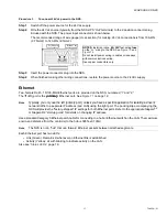
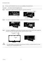
Procedure 3
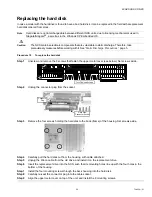
To connect 24 Vdc power to the NXS.
Step 1
Switch off the power source for the 24 Vdc supply.
Step 2
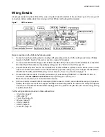
Wire the 24 Vdc source (typically from the NXS-UPS “Out” terminals) to the 2-position connector plug
included with the NXS. The power input connector is shown below.
The recommended range of wire gauge (cross section) for making 24 Vdc connections is from 18 AWG
(0.75mm2) to 14 AWG (2.5mm2).
Step 3
Insert the power connector plug into the NXS.
Step 4
When finished making other wiring connections, restore the power source to the 24 Vdc supply.
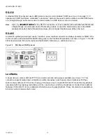
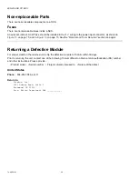
Ethernet
Two, female RJ-45, 10/100-Mbit Ethernet ports are provided on the NXS, numbered “1” and “2.”
The
1
(left) port is the
primary
Ethernet port. See
Note
Typically, you
only use the left
(primary port), unless you have a specific application for isolating a driver’s
network traffic to a separate IP address (and LAN) using the right port. The packing slip accompanying the
NXS will provide the “factory-shipped” IP settings for both Ethernet ports. Refer to the
appropriate
Niagara
AX
or Niagara R2 “startup guide” for details on changing IP address.
Use a standard Category 5 Ethernet patch cable for connecting to a hub or Ethernet switch on the LAN. The maximum
end-to-end distance from the controller to the hub is 328 feet (100m).
Note
The NXS is
not
a “hub” that can forward Ethernet packets between attached segments.
Each Ethernet port has two LEDs:
•
Link (Green): Remains lit whenever an Ethernet link is established.
•
Activity (Yellow): Lit with blinking to indicate activity on the LAN.
M (24V– in)
L+ (24V+ in)
NOTES:
Install an inline,
4A
,
32V
fast-acting
fuse
on the “L+” wiring to the NXS. See
and
Do not install power wiring in cables or raceways
with communications wiring.
Use copper conductors only.