


W-NXS AND CP-NXS
11
74-4059—01
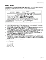
Wiring Details
All wiring is made to the front of the NXS—when mounted, this is the
bottom
for a layout of
connectors. Allow suitable slack for removing unit from DIN rail with wiring still connected.
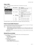
Figure 9
NXS Connectors.
Make connections to the NXS in the following order:
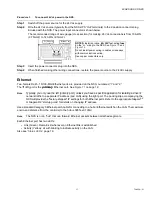
1.
Connect an earth grounding wire to a nearby earth grounding point, and to the earth ground screw (Phillips
head) on the NXS. See the
section on page 12 for details.
2.
Connect a standard USB A–B type cable between the NXS-UPS (if used) and one of the USB ports on the NXS.
Note that the UPS module must specifically configured. See
3.
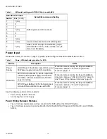
Prepare the 24Vdc power source. The LOGO!Power 24V/4A module is typically used for 24Vdc power. In most
cases, two additional modules are used for UPS backup operation during AC power outages: the SITOP DC-
USV-Modul 15 (UPS) and SITOP battery module. See the
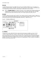
4.
Connect the Ethernet cable. The NXS provides two (2) auto-sensing 10BASE-T or 100BASE-TX (RJ-45)
connectors.
Use the
left
RJ-45 connector
as the primary port—see
.
Make this connection to your LAN (local area network).
5.
Other connectors include an RS-232 serial port (DB-9 connector, COM1) and an RS-485 serial port (3-position,
COM2). Both ports can be used to support serially-connected integrations. In addition, the LON port supports
connection to a LonWorks 78-Kbaud free topology (FTT-10) network, using the two-pin connector plug. Wiring
is polarity insensitive.
Further wiring details are provided in these subsections:
•
•
•
•
•
•
•
DVI/VGA
2.0 (4)
24Vdc
COM2
Primary
LAN 1
Secondary
Ethernet
LAN 2
Earth
Terminal
Mounting Point
FTT-10