background image

 Appendix A: List of Spares and Accessories

CIU 888

Part No.: 4417590_Rev13

4 - 2

Installation Manual

$*6

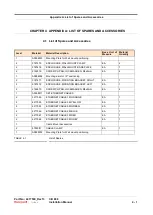
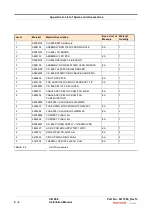
TABLE  4-2

List of Accessories

Level

Material

Material Description

Base  Unit  of

Measure

Material

Quantity

1

S0888104

CIU 888 BPM Field Board

2

0888104

ASSEMBLY, BPM FIELD CARD MODULE

EA

1

1

S0888103

CIU 888 LCD BOARD

2

0888103

ASSEMBLY, LCD PCB

EA

1

1

S0888105

CIU 888 RS232/485 Field BOARD

2

0888105

ASSEMBLY, RS232/485 FIELD CARD MODULE

EA

1

1

S0888108

CIU 888 TRL2 SPARE FIELD BOARD

1

1

S0888605

CIU 888 BATTERY PIGGYBACK BOARD-PWA

2

0888605

PIGGY BACK PCB

EA

1

2

2695199

PCB SUPPORT LOCKING TEARDROP 7/16"

EA

1

1

S0888902

CIU 888 SET OF 2 KEYLOCKS

2

0888501

CABLE ASSY, KEYLOCK SWITCH, W&M

EA

1

2

0888504

CABLE ASSY, KEYLOCK SWITCH, 

CONFIGURATION

EA

1

1

S0888905

FUSE 250V UL SLOBLO 5X20MM 2A

2

2656018

FUSE DRWR FOR PWR MOD F'GRIP 2PL

EA

1

2

2655084

FUSE 250V UL SLOBLO 5x20MM 2A

EA

2

1

S0888906

COMPACT FLASH, 4G

2

2849906

COMPACT FLASH, 4G

EA

1

1

S0888907

CIU 888 POWER  THERMAL PAD

2

3862297

AC-DC POWER SUPPLY 75W 12VDC

EA

1

2

6406013

SCREW PAN PH, M3x5mm

EA

4

2

6476503

CIRCLIP, M3SS DIN125A-A2

EA

4

2

0187509

THERMAL PAD 195.0x33.0x1.0mm

EA

1

Содержание CIU 888

Страница 1: ... 6 Installation Guide Release R160 ...

Страница 2: ...PTER 3 Electrical Installation 3 1 3 1 Grounding 3 1 3 2 Mains 3 1 3 3 CIU 888 Interface Summary 3 2 3 4 Field and Host Port Connections 3 3 3 5 Host RS232 485 Ports MODBUS Output 3 9 3 6 Ethernet Ports 3 9 3 7 USB Ports 3 10 3 8 VGA Port Optional Interface Part of a future release 3 10 3 9 Audio Port Part of a future release 3 10 3 10 Audio Plug and Signal Details Part of a future release 3 10 3 ...

Страница 3: ...Table of Contents Installation Manual Part No 4417590_Rev13 2 CIU 888 6 This page is intentionally left blank ...

Страница 4: ...tely notify the carrier If any equipment is missing or incorrect notify the Honeywell Enraf distributor As soon as you receive the box open it and check the contents right away Check the contents against the factory checklist and not only from the type plate 1 2 Storage Store the CIU 888 in its original packing indoors in a safe dry place Storage temperature may vary between 20 C and 85 C 4 F and ...

Страница 5: ...Storage Unpacking and Handling Handling CIU 888 Part No 4417590_Rev13 1 2 Installation Manual 6 This page is intentionally left blank ...

Страница 6: ... installation Honeywell Enraf accepts no responsibility caused by mis handling mis use or faulty operation of the CIU 888 2 2 Specifications and operational requirements Sl No Measure Value Units CIU 888 unit 1 Dimensions l x b x h 400 x 283 x 94 mm 15 X 11 x 3 in 2 Height 2U 3 Weight without accessories 7 5 kg 15 43 lb Wall mount 1 Wall Mount Base Plate l x b x h 267 x 455 x 84 mm 2 Horizontal mo...

Страница 7: ...ions and operational requirements CIU 888 Part No 4417590_Rev13 2 2 Installation Manual 6 2 2 1 CIU 888 Dimensions FIGURE 2 1 CIU 888 dimensions 400 153 4 in 283 11 1 8 in 90 31 2 in SPACE REQUIRED FOR CONNECTION 87 3 3 8 in 94 3 5 8 in ...

Страница 8: ...The CIU 888 is grounded via the earth wire of the mains cable and an external ground terminal is provided which is located at the rear side next to the mains power entry 2 5 Mounting You can mount the CIU 888 can in three different ways Table top or desktop use 19 rack mount Wall mount In any case the front panel of the CIU 888 must be freely accessible The front panel includes the LCD display use...

Страница 9: ...tory you can order it anytime as an accessory See the accessory list provided in this manual FIGURE 2 2 Rack Mounting The steps below show the rack mount bracket assembly with the unit 1 Fix the left bracket provided as part of rack mount accessories on the bottom of the CIU 888 by fastening the screws Repeat the same process for fixing the right bracket on the other side 6 8 in 400 15 in 465 18 i...

Страница 10: ...ion Mounting Part No 4417590_Rev13 CIU 888 Installation Manual 2 5 6 FIGURE 2 3 Fixing the Brackets 2 Mount the CIU 888 on the rack and align the screws to the holes FIGURE 2 4 Align with Rack Holes and tighten the screws ...

Страница 11: ...onsists of the following parts Wall Mount Base Plate Wall Mount Clamps For accessibility of the front panel and recommendations for cooling with the heat pipe follow these recommendations The height of the front panel must be suitable enough for you to have clear visibility and free access of the front panel Mount the base plate horizontally so that it ensures that the CIU 888 is also mounted hori...

Страница 12: ...URE 2 6 Marking Key Holes 2 Locate the Wall Mount Base Plate over screws and fasten the screws on top and bottom as illustrated in the following figure 410 mm 186 mm 261 mm HORIZONTAL TO THE FLOOR MUST BE AT A HEIGHT SO THAT THE DISPLAY IS CLEARLY VISIBLE TO THE USER 455 mm 84 mm 110 mm 267 mm ...

Страница 13: ...IGURE 2 7 Installing the Wall Mount Base Plate 3 Mount the unit to the wall mount bracket First the wall mount base plate assembly is hung on the wall by means of key slot openings Foam pads are provided on the face and bottom side of the bracket to provide cushioning to the unit FIGURE 2 8 ...

Страница 14: ... plate to the wall mount clamp by means of fasteners FIGURE 2 9 5 Repeat the process for the other clamp as well 6 The wall mount clamps are fixed to the base of the unit by means of fasteners on the either sides FIGURE 2 10 7 Place the unit on the wall mount plate by supporting it on the base of the plate ...

Страница 15: ...stallation Manual 6 FIGURE 2 11 Unit on the Wall Mount Base Plate NOTE Ensure that the top cover is secured behind the tab provided on the base plate so that the unit cannot be removed without lifting it FIGURE 2 12 Unit is placed behind the tab provided on the base plate ...

Страница 16: ...ual 2 11 6 8 After placing the unit on the Wall Mount Base Plate engage the hook to the latch keeper FIGURE 2 13 Latch the Hooks NOTE Loosen the nut behind the hook to adjust the height of the hook CAUTION Ensure the hook positions on both sides are main tained at the same length ...

Страница 17: ...CIU 888 Part No 4417590_Rev13 2 12 Installation Manual 6 9 Press the latching clip on both sides to snap with the hook Once it is snapped with the clip the hook is pulled back and the unit is held securely FIGURE 2 14 Securing the Unit ...

Страница 18: ... Part No 4417590_Rev13 CIU 888 Installation Manual 2 13 6 10 All the cables terminating on the CIU 888 unit are tied to the mounting bracket using the slots with cable ties as shown in the following figure FIGURE 2 15 Cable Tray 90mm ...

Страница 19: ...Mechanical Installation Mounting CIU 888 Part No 4417590_Rev13 2 14 Installation Manual 6 This page is intentionally left blank ...

Страница 20: ...ons of 10 and 15 are allowed The power supply unit inside the CIU 888 detects to which supply it is connected and automatically switches over to the correct setting The mains block contains two fuses one on line and other on neutral size Ø5 x 20 mm both rated 1 6 A slow blow T1 6 A L 250 V in accordance with IEC 60127 2 III Fuse Details Part 0239002 MXP Make Littelfuse Description FUSE 250 V UL SL...

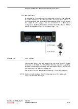
Страница 21: ..._Rev13 3 2 Installation Manual 6 3 3 CIU 888 Interface Summary FIGURE 3 1 CIU 888 Interface Summary Sync Port Bezel LCD Display ESC Button Navigation Buttons Service Port USB Port W M Key Lock Configuration Key Lock W M Key Configuration Key Product Label CIU 888 Front View ...

Страница 22: ...is connected in a star configuration Refer to FIGURE 3 2 Enraf Field Bus Board BPM Board can be placed in any of the option slots 1 6 FIGURE 3 2 Enraf Field Bus BPM Port Connect the Enraf Field bus cable to the two outer terminals of the connector at the Field Port The Enraf field bus signal is not polarity sensitive The shield dotted lines of the Enraf field bus cable must be connected to the cen...

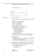
Страница 23: ... Connection FIGURE 3 3 Enraf Field Bus connection It is recommended to use the following cable specifications for effective results One twisted and shielded pair cable Rmax 200 per line Cmax 1 uF to each other and to ground NOTE To prevent cross talk only individually shielded twisted pairs should be used in a multi core cable ...

Страница 24: ... a Multi drop configuration Refer to FIGURE 3 2 TRL 2 Field Bus Board TRL 2 Board can be placed in any of the option slots 1 6 FIGURE 3 4 TRL 2 Field Bus Connect the TRL 2 Field bus cable to the two outer terminals of the connector at the Field Port The TRL 2 field bus signal is not polarity sensitive The shield of the TRL 2 field bus cable must be connected to the centre terminal Refer to FIGURE ...

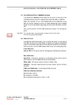
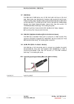
Страница 25: ...8 AWG 4 km Belden 8762 20 AWG 3 km Belden 88761 22 AWG 2 km Belden 88641 24 AWG 1 km Stub not 100 meters No of strands 7 or 19 or more higher better performance Shielded connection Earthed towards Host system FCU FBM 3 4 3 Field RS232 485 Port A RS232 485 Field Board for connection to a CIU 888 Communications Interface Unit can be placed in any of the option slots 1 to 6 These ports have galvanic ...

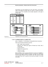
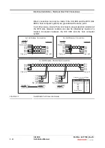
Страница 26: ... metre with a ground wire Overall shielded Rmax 0 12 m per line Cmax 119 pF m Lmax 1 45 mH m Refer FIGURE 3 7 A for full duplex RS 485 connection or FIGURE 3 7 B when a half duplex RS 485 connection is required For half duplex connect signals RXA with TXA and RXB with TXB inside the cable connectors Place 120 resistors at the receive terminals in the cable connectors Signal Name Pin no 9 Pins 25 P...

Страница 27: ... computer system FIGURE 3 7 Field RS485 Port Connection Details CIU 888 female Prot Ground TXA TXB RXA RXB Sign gnd DTE DCE RXA RXB TXA TXB Sign gnd A Full Duplex Connection 120 E 120E female Prot Ground TXA TXB RXA RXB Sign gnd DTE DCE RXA RXB TXA TXB Sign gnd B Half Duplex Connection TXA TXB RXA RXB Sign gnd RXA RXB TXA TXB Sign gnd C Half Duplex Multi drop connection 120 E 120 E TXA TXB RXA RXB...

Страница 28: ...d Host Ports are not galvanically isolated 3 6 Ethernet Ports CIU 888 has 6 Ethernet ports one on front side and 5 on rear side of CIU 888 All ports are 10 100 Mbps compliant and support Auto MDIX support auto detects Straight or Cross cable and switches accordingly See the section 3 3 CIU 888 Interface Summary for locating the ports Front Side Port Service Port This port is used for debugging and...

Страница 29: ...ack Two Ports Current Limit 200 mA Part of a future release Front One Port Current Limit 500 mA 3 8 VGA Port Optional Interface Part of a future release CIU 888 has a standard VGA port to connect to a VGA monitor The maximum resolution supported is 1920x1200 See the section 3 3 CIU 888 Interface Summary for locating this connector 3 9 Audio Port Part of a future release CIU 888 has a 3 5 mm Audio ...

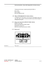
Страница 30: ...tputs Part of a future release CIU 888 has two relay outputs They are also called digital outputs as they offer make or break connections Refer to port details chapter for locating this connector 3 11 1 Relay Contact Specification Part of a future release DPDT Type Relay Rated DC Switching Voltage 30VDC Rated DC Current 1A Minimum Switching Operations 50000 3 11 2 Relay Layout FIGURE 3 9 Relay Lay...

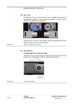
Страница 31: ... shown below Key pull is possible in both positions Spare keys for both keys are available and are supplied with the unit Store the spare keys in a secure location FIGURE 3 10 W M and Configuration Key Locks 3 13 User Interface LCD Navigation Key Ring of Light CIU 888 on its front bezel has an LCD module and Key pad for user interface and configuration A Ring of light to display status FIGURE 3 11...

Страница 32: ...button in center and also a separate Esc Escape button to operate the screens on LCD 3 13 2 Ring of Light CIU 888 has Ring of Light to display operation status This ring of light is constructed with RGB LEDs As a part of a future release CIU 888 will be designed to display NAMUR colors Green Blue Yellow Orange and Red along with a few patterns like Standstill Blink Snooze and Clockwise rotation NO...

Страница 33: ...Electrical Installation User Interface CIU 888 Part No 4417590_Rev13 3 14 Installation Manual 6 This page is intentionally left blank ...

Страница 34: ...ASE PLATE EA 1 2 2146979 SCREW PH PAN LOCKWASHER M4x6mm EA 4 1 A0888904 Mounting ears for 19 positioning 2 0187471 ENCLOSURE MOUNTING BRACKET RIGHT EA 1 2 0187472 ENCLOSURE MOUNTING BRACKET LEFT EA 1 2 2146979 SCREW PH PAN LOCKWASHER M4x6mm EA 4 1 A0888911 SET ETHERNET CABLES 2 4217063 ETHERNET CABLE 1M ORANGE EA 1 2 4217065 ETHERNET CABLE 3M YELLOW EA 1 2 4217064 ETHERNET CABLE 3M GREEN EA 1 2 42...

Страница 35: ...LD BOARD 1 1 S0888605 CIU 888 BATTERY PIGGYBACK BOARD PWA 2 0888605 PIGGY BACK PCB EA 1 2 2695199 PCB SUPPORT LOCKING TEARDROP 7 16 EA 1 1 S0888902 CIU 888 SET OF 2 KEYLOCKS 2 0888501 CABLE ASSY KEYLOCK SWITCH W M EA 1 2 0888504 CABLE ASSY KEYLOCK SWITCH CONFIGURATION EA 1 1 S0888905 FUSE 250V UL SLOBLO 5X20MM 2A 2 2656018 FUSE DRWR FOR PWR MOD F GRIP 2PL EA 1 2 2655084 FUSE 250V UL SLOBLO 5x20MM ...

Страница 36: ...Phone 1 800 423 9883 or 1 215 641 3610 E mail HFS TAC SUPPORT honeywell com Copyright 2020 Honeywell All rights reserved No part of this manual may be reproduced in any form by print photoprint microfilm or any other means without the written permission from Honeywell ...

Страница 37: ... Houston Pkwy S Houston TX 77042 USA Phone 1 480 293 2042 Email enraf us honeywell com Europe Middle East and Africa Honeywell Enraf Delftechpark 39 2628 XJ Delft the Netherlands Phone 31 0 15 2701 100 Email enraf nl honeywell com Asia Pacific Honeywell Pte Ltd 17 Changi Business Park Central 1 Singapore 486073 Phone 65 6355 2828 Email enraf sg honeywell com 4417590_Rev13 June 2020 2020 Honeywell ...

Отзывы: