background image

BENDIX/KING

KI 208, KI 209

Rev 4, Aug 2002

IM 006-00140-0004

RH-2

THIS PAGE RESERVED

RELEASED FOR THE EXCLUSIVE USE BY: AIRCRAFT ELECTRONICS ASSOCIATION

UP536434

Содержание Bendix

Страница 1: ...INSTALLATION MANUAL KI 208 KI 209 NAVIGATION INDICATORS MANUAL NUMBER 006 00140 0004 Revision 4 August 2002 h RELEASED FOR THE EXCLUSIVE USE BY AIRCRAFT ELECTRONICS ASSOCIATION UP536434 ...

Страница 2: ...N OF THIS PUBLICATION OR ANY PORTION THEREOF BY ANY MEANS WITHOUT THE EXPRESS WRITTEN PERMISSION OF HONEYWELL IS PROHIBITED FOR FURTHER INFORMATION CONTACT THE MANAGER TECHNICAL PUBLICATIONS HONEYWELL ONE TECHNOLOGY CENTER 23500 WEST 105TH STREET OLATHE KS 66061 TELEPHONE 913 782 0400 RELEASED FOR THE EXCLUSIVE USE BY AIRCRAFT ELECTRONICS ASSOCIATION UP536434 ...

Страница 3: ...ING KI 208 KI 209 Navigation Indicators PART NUMBER REV DATE DESCRIPTION 006 00140 0004 4 Aug 2002 Replaces P N 006 00140 0003 006 00140 0003 3 Oct 1996 Replaces P N 006 00140 0002 006 00140 0002 2 Mar 1988 Replaces P N 006 00140 0001 RELEASED FOR THE EXCLUSIVE USE BY AIRCRAFT ELECTRONICS ASSOCIATION UP536434 ...

Страница 4: ...BENDIX KING KI 208 KI 209 Rev 4 Aug 2002 IM 006 00140 0004 RH 2 THIS PAGE RESERVED RELEASED FOR THE EXCLUSIVE USE BY AIRCRAFT ELECTRONICS ASSOCIATION UP536434 ...

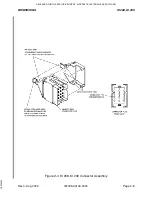
Страница 5: ...ION Paragraph Page 2 1 General 2 1 2 2 Unpacking and Inspecting Equipment 2 1 2 3 Installation KI 208 KI 209 2 1 2 4 Post Installation Checkout 2 2 LIST OF TABLES Table Page 2 1 ILS Deflection 2 3 2 2 Glideslope Deflection 2 3 LIST OF ILLUSTRATIONS Figure Page 2 1 KI 208 Pinout List 2 5 2 2 KI 209 Pinout List 2 6 2 3 Crimping Tool 2 7 2 4 KI 208 KI 209 Connector Assembly 2 8 2 5 KI 208 KI 209 Outl...

Страница 6: ...TION III OPERATION Paragraph Page 3 1 Equipment Operation 3 1 3 2 Indicator Control Functions KI 208 KI 209 3 2 LIST OF ILLUSTRATIONS Figure Page 3 1 KI 208 Control Functions 3 3 3 2 KI 209 Control Functions 3 4 RELEASED FOR THE EXCLUSIVE USE BY AIRCRAFT ELECTRONICS ASSOCIATION UP536434 ...

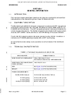
Страница 7: ...g of the visual indicator The KI 209 ILS Indicator performs the same functions as the KI 208 In addition it contains an UP DOWN glideslope needle with an OFF warning flag An anti reflective lens coating is also available on some models of the KI 208 and KI 209 1 3 TECHNICAL CHARACTERISTICS TABLE 1 1 Technical Characteristics KI 208 KI 209 SPECIFICATION CHARACTERISTIC KI208 KI209 TSO COMPLIANCE C40...

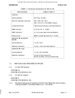
Страница 8: ...racy OMNI Sensitivity External Load 50 k ohms nominal LOC 0 33 10 Vrms VOR 0 50 10 Vrms ARINC phased 4 dB tone ratio will give 3 dot scale deflection 2 max error 1 typical 10 off course gives full scale deflection ARINC autopilot deviation two 1 k loads GLIDESLOPE DEVIATION METER Input Impedance Deflection Sensitivity 1 k 5 ohms 150 5 uA for full scale deflection GLIDESLOPE FLAG Input Impedance De...

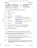
Страница 9: ...ing 1 5 8 Crimp Tool Burndy Hytool M8ND 1 5 9 Extraction Tool Handle P N 005 02012 0012 Burndy RXT20 4P3 1 5 10 Extraction Tool Tip P N 005 02012 0013 Burndy RXK20 25 1 6 LICENSE REQUIREMENTS None 1 7 REQUIREMENTS FOR TSO D VOR ILS GLIDESLOPE SYSTEM Units used in conjunction with the KI 208 KI 209 must meet the specifications listed below to comprise a completely TSO d navigation system 1 7 1 Navi...

Страница 10: ... paragraph 2 1 sub paragraph b Centering Accuracy 1 7 2 3 Deviation current with a 700 uV Standard Glideslope Deviation Signal 0 091 0 001 ddm tone ratio applied to the receiver input shall be 78 10 uA into a 1000 ohm load Deviation current shall not change more than 15 as the RF input level of a Standard Glideslope Deviation Signal is varied from 100 to 10 000 uV Deviation current shall be propor...

Страница 11: ...lect the KI 208 KI 209 panel location for unobstructed vision min imum parallax and adequate clearance for the instrument case and installa tion of cables and connectors 2 3 1 2 Refer to Figure 2 5 P N 155 05235 0000 or other appropriate drawing for the KI 208 and KI 209 mounting dimensions 2 3 1 3 A standard 3 1 8 inch instrument hole is required Refer to Figure 2 5 P N 155 05235 0000 or other ap...

Страница 12: ...nded after installation to insure satisfactory performance of the equipment in its normal environment 2 4 1 RAMP TEST 2 4 1 1 Use VOR ILS ramp generator IFR 401L or equivalent 2 4 1 2 Set ramp generator to VOR 90 TO Set NAV receiver to VOR frequency Rotate OBS until the D bar centers with the To From indicator reading TO The OBS should read 90 TO 2 Change the generator to 0 TO center the D bar and...

Страница 13: ...VOR audio and insure that no electrical interference such as magneto noise is present Check the tone identifier operation Fly inbound or outbound on a selected VOR radial and check for proper LEFT RIGHT and TO FROM indications Check VOR accuracy for 5 of a known heading NOTE VOR ground station scalloping may occur under weak signal conditions Channel off VOR NAV receiver and verify that the NAV wa...

Страница 14: ...ng a simulated ILS approach Check local izer LEFT RIGHT deflection and if applicable glideslope deflection Check the localizer accuracy in relation to the ILS runway Channel off ILS NAV receiver and verify that NAV GS warning flag s appear RELEASED FOR THE EXCLUSIVE USE BY AIRCRAFT ELECTRONICS ASSOCIATION UP536434 ...

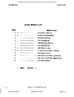
Страница 15: ...BENDIX KING KI 208 KI 209 Rev 4 Aug 2002 IM 006 00140 0004 Page 2 5 Figure 2 1 KI 208 Pinout List RELEASED FOR THE EXCLUSIVE USE BY AIRCRAFT ELECTRONICS ASSOCIATION UP536434 ...

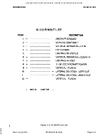
Страница 16: ...BENDIX KING KI 208 KI 209 Rev 4 Aug 2002 IM 006 00140 0004 Page 2 6 Figure 2 2 KI 209 Pinout List RELEASED FOR THE EXCLUSIVE USE BY AIRCRAFT ELECTRONICS ASSOCIATION UP536434 ...

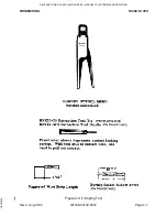
Страница 17: ...BENDIX KING KI 208 KI 209 Rev 4 Aug 2002 IM 006 00140 0004 Page 2 7 Figure 2 3 Crimping Tool RELEASED FOR THE EXCLUSIVE USE BY AIRCRAFT ELECTRONICS ASSOCIATION UP536434 ...

Страница 18: ...BENDIX KING KI 208 KI 209 Rev 4 Aug 2002 IM 006 00140 0004 Page 2 8 Figure 2 4 KI 208 KI 209 Connector Assembly RELEASED FOR THE EXCLUSIVE USE BY AIRCRAFT ELECTRONICS ASSOCIATION UP536434 ...

Страница 19: ...BENDIX KING KI 208 KI 209 Rev 4 Aug 2002 IM 006 00140 0004 Page 2 9 FIGURE 2 5 KI 208 KI 209 Outline and Mounting Drawing Dwg No 155 05235 0000 Rev 4 UP536434 ...

Страница 20: ...BENDIX KING KI 208 KI 209 Rev 4 Aug 2002 IM 006 00140 0004 Page 2 11 FIGURE 2 6 KI 208 KI 209 Typical Interconnect UP536434 ...

Страница 21: ...BENDIX KING KI 208 KI 209 Rev 4 Aug 2002 IM 006 00140 0004 Page 2 13 FIGURE 2 7 KI 208 Non TSO d Silver Crown System Interconnect Dwg No 155 01223 0000 Rev 4 UP536434 ...

Страница 22: ...BENDIX KING KI 208 KI 209 Rev 4 Aug 2002 IM 006 00140 0004 Page 2 15 FIGURE 2 8 KI 209 System Interconnect Dwg No 155 01241 0000 Rev 4 UP536434 ...

Страница 23: ... course To the station If the deviation nee dle moves to the right the aircraft course must be adjusted 5 or 10 degrees to the right Similarly if the deviation needle goes to the left the aircraft course must be adjusted to the left Maintaining a centered deviation needle will provide automatic course com pensation for wind drift 3 1 2 LOCALIZER OPERATION KI 208 KI 209 Localizer circuits are autom...

Страница 24: ...ays the control functions of the KI 208 Figure 3 2 displays the control functions of the KI 209 3 2 1 OMNI BEARING SELECTOR OBS The OMNI Bearing Selector knob rotates the azimuth card on which the desired course is selected The course selected serves as a reference for all VOR indications The reciprocal course is identified under the bottom course index 3 2 2 VOR LOC DEVIATION INDICATOR The VOR LO...

Страница 25: ...BENDIX KING KI 208 KI 209 Rev 4 Aug 2002 IM 006 00140 0004 Page 3 3 Figure 3 1 KI 208 Control Functions RELEASED FOR THE EXCLUSIVE USE BY AIRCRAFT ELECTRONICS ASSOCIATION UP536434 ...

Страница 26: ...BENDIX KING KI 208 KI 209 Rev 4 Aug 2002 IM 006 00140 0004 Page 3 4 Figure 3 2 KI 209 Control Functions RELEASED FOR THE EXCLUSIVE USE BY AIRCRAFT ELECTRONICS ASSOCIATION UP536434 ...

Отзывы: