
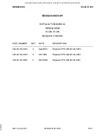


BENDIX/KING
KI 208, KI 209
Rev 4, Aug 2002
IM 006-00140-0004
Page 2-1
SECTION II
INSTALLATION
2.1
GENERAL
This section contains suggestions and factors to consider before installing the KI 208,
KI 209 Indicator. Close adherence to these suggestions will assure a more satisfac-
tory performance from the equipment.
2.2
UNPACKING AND INSPECTING EQUIPMENT
Exercise extreme care when unpacking each unit. Make a visual inspection of each
unit for evidence of damage incurred during shipment. If a claim for damage is to be
made, save the shipping container to substantiate the claim. When all equipment is
removed, place in the shipping container all packing materials for use in unit storage
or reshipment. The KI 208, KI 209 installation will conform to standards designated by
the customer, installing agency and existing conditions as to unit location and type of
installation.
NOTE
This equipment has plastic lenses. Use extreme
caution when cleaning.
2.3
INS
TALLATION
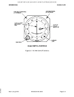
KI 208, KI 209
2.3.1
Installation Procedure
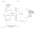
2.3.1.1
Carefully select the KI 208, KI 209 panel location for unobstructed vision, min-
imum parallax, and adequate clearance for the instrument case and installa-
tion of cables and connectors.
(P/N 155-05235-0000), or other appropriate drawing, for
the KI 208 and KI 209 mounting dimensions.
2.3.1.3 A standard 3 1/8 inch instrument hole is required.
(P/N
155-05235-0000), or other appropriate drawing, for hole punch or filing tem-
plates.
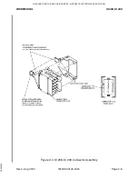
2.3.1.4
Secure the KI 208, KI 209 firmly in place using the mounting screws supplied.
If the mounting screw supplied are not used, #6-32 mounting screws that do
not extend more than 0.625 inches (1.59 cm) into the unit may be used.
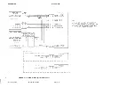
2.3.1.5
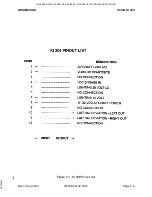
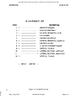
The installing agency will supply and fabricate the external cable. The plugs
required are supplied by Bendix/King.
2.3.1.6
The KI 208, KI 209 will drive two external deflection indicator loads of 1000
ohms or greater impedance.
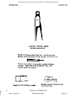
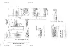
2.3.1.7
An omni phase adjust potentiometer, R233 is accessible from the front of the
indicator by removing the upper left mounting screw. The 2 1/2 inch long ad-
justment tool (P/N 088-00706-0000) is required to adjust the omni phase ad-
RELEASED FOR THE EXCLUSIVE USE BY: AIRCRAFT ELECTRONICS ASSOCIATION
UP536434


