


STEP 4. INSTALL INLET TUBE
The inlet tube (shown in Figure 3) is identified by a series of air inlet holes on the tube. This tube must be purchased sep-
arately. Order the correct length, as specified in Table 1, for the width of the duct where it will be installed. The exhaust
tube is molded into the base of the duct housing.
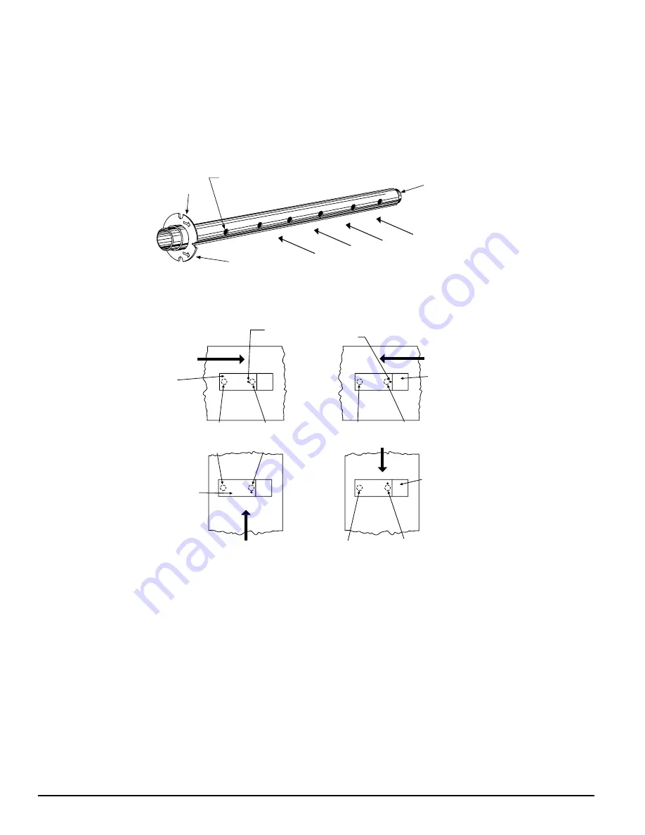
The inlet tube should be installed in the inlet sampling tube bushing located in the center of the duct detector housing.
(See Figure 2A.) The air inlet holes must face into the air flow. To assure proper installation, the tube mounting flange is
marked with arrows. Mount the inlet tube so that the arrows point into the air flow. Figure 4 shows the various combina-
tions of duct detector and tube mounting configurations with respect to air flow.
A78-2047-00
Figure 3. Air Duct Detector Inlet Sampling Tube.
A78-1812-01
Figure 4. Tube Mounting Configurations with Varying Air Flow Direction and Orientation of Detector Housing.
Vertical as well as Horizontal Mounting is Acceptable.
A. INSTALLATION FOR DUCTS LESS THAN 8 (2.4 M) FEET WIDE
1. If the inlet tube is longer than the width of the air duct, drill a 3/4-inch (19 mm) hole in the duct directly opposite the
hole already cut for the inlet tube.
If the inlet tube is shorter than the width of the air duct, install the end cap into the inlet tube as shown in Figure 3.
2. Slide the inlet tube into the bushing located in the center of the duct housing. Position the tube so that the arrows
point into the air flow.
3. Secure the tube flange to the housing bushing with the two #6 self-tapping screws.
4. For tubes longer than the width of the air duct, the tube should extend out of the opposite side of the duct. If there
are more than 2 holes in the section of the tube extending out of the duct, select a different tube length using Table
1. Otherwise, trim the end of the tube protruding through the duct so that 1 to 2 in (25 to 51 mm) of the tube extends
outside the duct. Plug this end with the tube end plug and tape closed any holes in the protruding section of the tube.
Be sure to seal the duct when the tube protrudes.
5. Any inlet tube over 3 ft (91 cm) long must be supported on the opposite side of the duct detector housing.
AIR FLOW
DIRECTION
DUCT
DETECTOR
HOUSING
DOTS INDICATE POSITION OF
SAMPLING TUBE HOLES
AIR FLOW
DIRECTION
DUCT
DETECTOR
HOUSING
INLET
TUBE
EXHAUST
TUBE
AIR FLOW
DIRECTION
INLET
TUBE
EXHAUST
TUBE
INLET
TUBE
EXHAUST
TUBE
DUCT
DETECTOR
HOUSING
AIR FLOW
DIRECTION
EXHAUST
TUBE
INLET
TUBE
DUCT
DETECTOR
HOUSING
INLET
TUBE
END
PLUG
AIR HOLES
ARROWS
MUST FACE
INTO AIR FLOW
AIR FLOW DIRECTION
FLANGE
A78-1994-02
Figure 9. SSDRTS451/SSDRTS451KEY Test Coil Installation
SSDMOD400R SENSITIVITY TEST
After verification of alarm capability, use the SSDMOD400R test module with a voltmeter to check detector sensitivity as
indicated in the SSDMOD400R installation manual. The housing cover must be removed to perform this test.
If the SSDMOD400R readings indicate that the sensor head is outside of the acceptable range, the sensor heads require
cleaning. (Refer to PERIODIC MAINTENANCE REQUIREMENTS).
TROUBLE TEST
The capability of Trouble detection is tested by removing the detector head from the duct housing. The detector head is
removed by turning it counterclockwise about 10 degrees (Figure 8). The system control panel should indicate a trouble
condition. Replacing the detector head should clear the trouble condition.
STEP 8. INSTALL THE COVER
Install the cover using the four screws. Be certain filters are installed as specified in Step 6. Make sure that the cover fits
into the base groove and that all gaskets are in their proper positions. Tighten the four cover screws to 10 in-lbs.
STEP 9. PERFORM THE FINAL SYSTEM CHECK
Position the magnet as shown in Figure 7. The LEDs on the detector should light. Any accessory LED(s) should also light.
The system control panel should indicate an alarm condition.
PERIODIC MAINTENANCE REQUIREMENTS
Air duct smoke detectors should be maintained at least once a year – more often if the detector heads become obviously
dirty. The detectors must also be cleaned immediately after a fire. Failure to properly maintain air duct smoke detectors
may cause unnecessary false alarms.
Honeywell recommends that a permanent Detector Test Log be set up and maintained for each individual smoke detec-
tor in each building. Each detector should be clearly described, with information on the type of detector, the model num-
ber, the serial number (if any), the location, and the type of environment. Data entries should include test dates, type of
test mode, test results, maintenance, and comments. A Detector Test Log is included at the end of this manual.
Recommended Detector Maintenance Procedure
NOTE: Notify the proper authorities that the smoke detector system is undergoing maintenance and will be temporarily
out of service. Disable the zone or system undergoing maintenance to prevent unwanted alarms and possible
dispatch of the fire department.
1. Turn off power to the system.
2. Remove and inspect sampling tube filters.
3. If filters are heavily coated with dirt, replace them with new filters. If they are not heavily coated, use a vacuum clean-
er or compressed air nozzle to remove dust, then install the filters.
4. Remove detector from housing. (See Figure 8.)
DETECTOR
HEAD
TEST COIL
H500-03-00
4
I56-475-09R
H500-03-00
9
I56-475-09R


